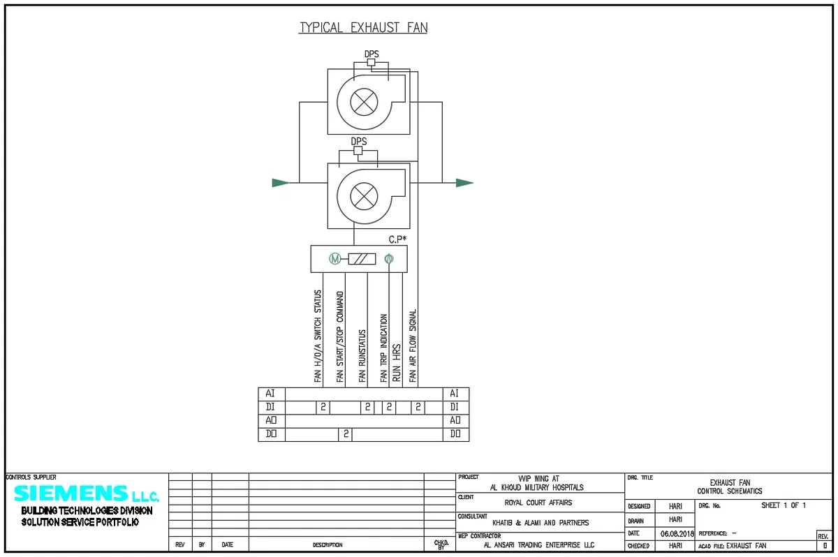
Typical Exhaust Air Fan Control DWG With DPS Run Status Signal

Ratings & Reviews
Be the first to share your experience with this product. Your review helps others make better decisions!
Description
This Typical Exhaust Air Fan Control DWG With DPS Run Status Signal drawing presents a clear control schematic for a standard exhaust ventilation system used in HVAC applications. The layout shows dual exhaust fan units connected in parallel, with airflow direction indicated and integrated differential pressure switches DPS for monitoring system performance. The control panel includes motor connections and essential signals such as fan HOA switch status, fan start stop command, fan run status, fan trip indication, run hours, and fan air flow signal for efficient system control. The schematic also highlights control points, wiring, and signal distribution through AI DI, AO, and DO interfaces, ensuring seamless building management system integration. Designed for reliable air extraction systems in commercial and industrial environments, this Typical Exhaust Air Fan Control DWG With DPS Run Status Signal provides a complete understanding of control logic, airflow monitoring, and operational feedback for engineers and designers.
Tags
Uploaded by:
Harriet
Burrows
Ratings & Reviews
Be the first to share your experience with this product. Your review helps others make better decisions!