Slaughter House CAD Plans with 74m Processing Block and Layouts
Tags
Ratings & Reviews
Be the first to share your experience with this product. Your review helps others make better decisions!
Description
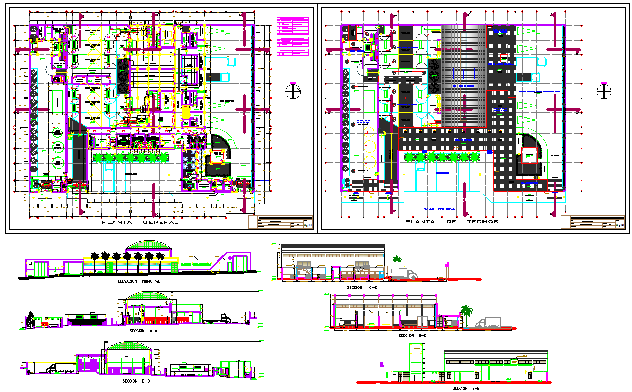
This municipal slaughterhouse CAD plan features a 74-meter-long primary processing block, designed with efficient circulation and hygienic operational flow. The general floor plan includes livestock reception areas, holding pens, stunning zones, slaughter corridors, and dedicated processing rooms. Structural gridlines, column points, and clear wall partitions define each activity zone with precision. The drawing also highlights equipment placements, water supply lines, sanitation points, inspection rooms, and staff movement passages necessary for maintaining regulatory compliance. The roof plan illustrates ventilation shafts, mechanical exhaust systems, and covered roofing segments arranged to ensure proper airflow and environmental control.
The elevation and sectional drawings provide detailed insight into building height, internal levels, service access route, and façade alignment. Multiple sectional views demonstrate waste disposal channels, drainage slopes, overhead rails, cold storage connections, and utility shafts positioned for efficient operations. Outdoor elements such as vehicle loading bays, service roads, and landscaped buffer zones are also represented. This DWG file is an essential resource for architects, civil engineers, facility planners, and consultants designing regulated meat processing environments. Suitable for AutoCAD, 3D Max, Revit, and SketchUp workflows, the plan supports conceptual design, engineering coordination, and construction documentation for municipal slaughterhouse projects.

Uploaded by:
Jafania Waxy
Tags
Ratings & Reviews
Be the first to share your experience with this product. Your review helps others make better decisions!