Detailed Raft Footing Layout with Structural Reinforcement DWG Plan
Tags
Ratings & Reviews
Be the first to share your experience with this product. Your review helps others make better decisions!
Description
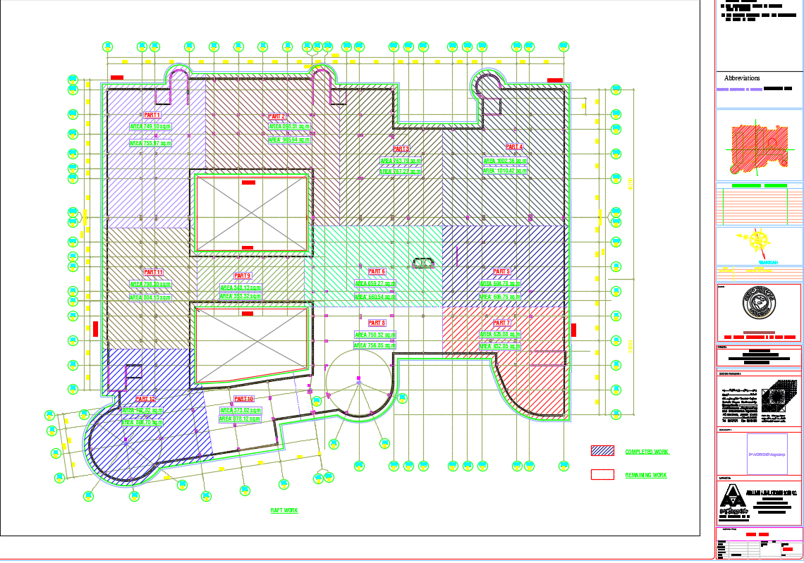
This AutoCAD DWG file presents a complete structural design of a raft footing layout plan, illustrating detailed reinforcement, grid lines, and section divisions. The drawing includes clear demarcation of completed and remaining work, labeled sections (Part 1 to Part 11), and corresponding area measurements in square meters. Each zone is defined with accurate boundary lines and load distribution details, ensuring structural stability and uniform load transfer across the foundation. The plan also indicates grid spacing, column positions, and reinforcement layout suitable for multi-story building projects.
Engineers and architects can use this drawing for foundation design analysis, construction supervision, or academic reference. The DWG file follows engineering standards, showing footing area measurements such as 755.87 sq.m., 970.92 sq.m., and 685.22 sq.m., with exact dimensions for reinforcement placement. This plan ensures the proper design of raft slabs that prevent differential settlement and improve load-bearing performance. Perfect for civil engineers, contractors, and students, this file enhances professional workflow and accuracy in project execution. Download this detailed raft footing AutoCAD DWG drawing for precise and efficient structural design implementation.

Uploaded by:
muhammad yousaf
Tags
Ratings & Reviews
Be the first to share your experience with this product. Your review helps others make better decisions!