Electrical layout design of modern commercial floor in DWG file
Description
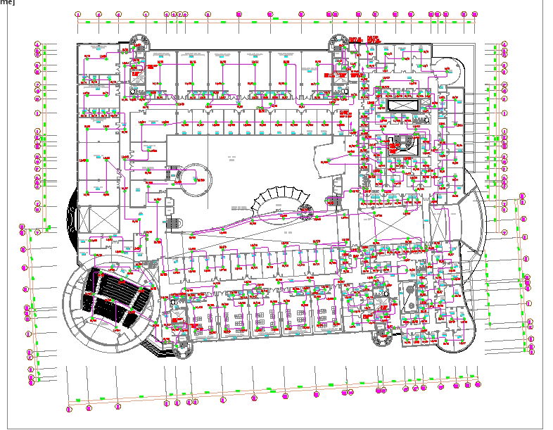
This CAD DWG file named ELECT'L-13 presents the complete electrical layout design of a modern commercial floor. The drawing displays detailed electrical circuits, switchboard connections, light points, and power distribution across various rooms. Each section of the plan including offices, conference areas, corridors, and entry spaces has been clearly marked with precise wiring routes, panel board positions, and lighting symbols. The circular hall and central staircase area add to the architectural complexity, making this file a valuable design reference for multi-utility buildings.
The plan further includes the external lighting arrangement and boundary pole layout surrounding the entire structure, ensuring a well-lit and safe environment. The organized wiring pattern enhances energy efficiency and simplifies maintenance procedures. This DWG file is ideal for architects, electrical engineers, and interior designers looking for an accurate and editable CAD resource for their commercial or office projects. Download this AutoCAD drawing to optimize your electrical design planning and execution with precision.
File Type:
DWG
File Size:
1.5 MB
Category::
Electrical
Sub Category::
Architecture Electrical Plans
type:
Free

Uploaded by:
muhammad
yousaf