Cold water hydraulic plumbing layout with multi floor pipeline plan
Tags
Ratings & Reviews
Be the first to share your experience with this product. Your review helps others make better decisions!
Description
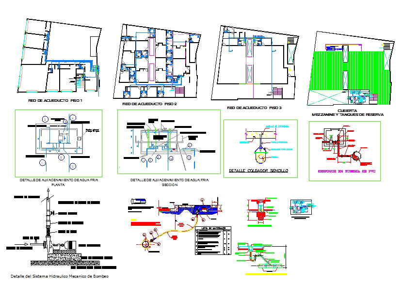
This cold water hydraulic plumbing layout illustrates a complete multi floor water supply arrangement, covering Floor 1, Floor 2 and Floor 3 with accurate pipe routing and measurement markings. The drawing shows the full cold water distribution path including entry points, valve positions, branch lines and riser connections for efficient flow management. The mezzanine level layout includes the reserve storage tanks placed with correct inlet, outlet and overflow piping. Additional details highlight anchoring positions, sectional pipe elevations, PVC connection points and water meter placement with clear line weights and directional arrows. These graphic representations ensure proper understanding of the plumbing network before site execution.
The drawing also features a mechanical pumping system layout showing pump alignment, suction pipe, delivery line, check valve, foot valve and pressure control components. A complete cold water storage detail in plan and section view explains the tank height, support structure and distribution lines feeding the building. Each element is designed to help architects, civil engineers, builders and MEP professionals create accurate plumbing installations. This detailed cold water layout enhances precision in drafting, improves installation accuracy and supports professional CAD work for residential or commercial hydraulic systems.

Uploaded by:
Harriet Burrows
Tags
Ratings & Reviews
Be the first to share your experience with this product. Your review helps others make better decisions!