Mechanical Shaft with Tapered Roller Bearing Section CAD Drawing
Ratings & Reviews
Be the first to share your experience with this product. Your review helps others make better decisions!
Description
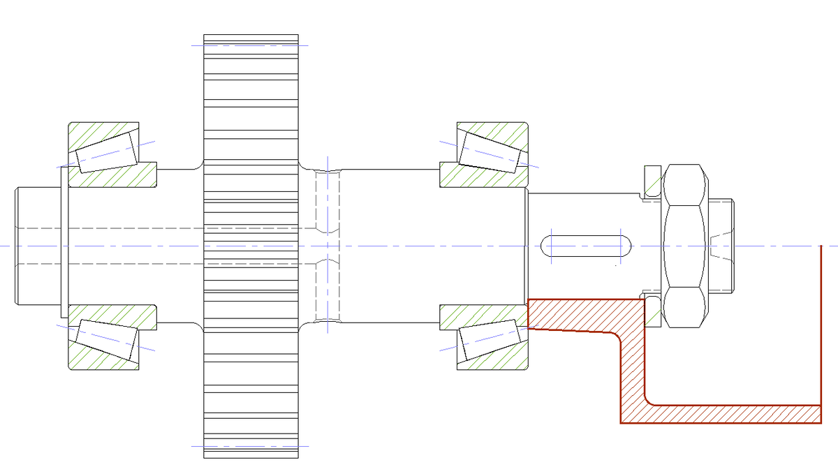
This mechanical shaft bearing assembly section drawing shows a horizontally aligned stepped shaft supported by tapered roller bearings on both ends. The sectional view clearly represents bearing cones, cups, spacers, and seating positions inside the housing. Centerlines indicate the shaft axis, while sectional hatching differentiates solid components such as the shaft, bearing races, and support blocks. The drawing also includes locking nut placement and end support detail, allowing a clear understanding of axial positioning and bearing arrangement within the assembly.
The AutoCAD DWG drawing accurately illustrates shaft diameter changes, bearing contact angles, and housing support geometry. Section cuts expose internal clearances and bearing alignment, making the assembly easy to read and interpret. The drawing layout maintains symmetry and proportional spacing between components, supporting precise mechanical drafting.
Tags
Uploaded by:
Ratings & Reviews
Be the first to share your experience with this product. Your review helps others make better decisions!