Industrial Pipeline Valve Layout Drawing With Flow Direction Details
Tags
Ratings & Reviews
Be the first to share your experience with this product. Your review helps others make better decisions!
Description
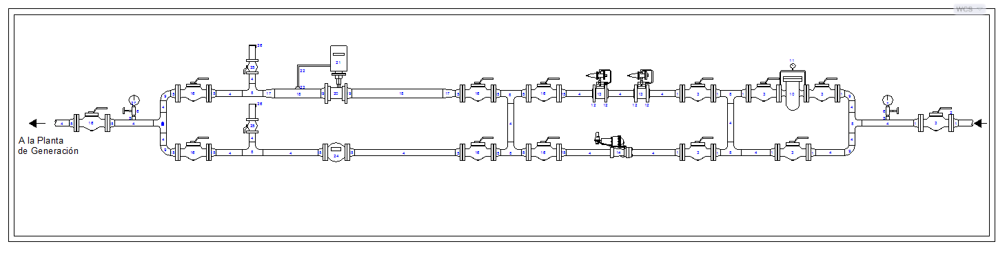
This AutoCAD DWG file contains a detailed industrial pipeline valve layout drawing designed for utility and process system applications. The drawing illustrates a complete linear piping arrangement with clearly marked flow direction, control valves, isolation valves, meters, joints, and connection points. Each component is accurately placed to show the operational sequence of the pipeline system. Dimensions are indicated in metric units, including pipe lengths, spacing between valves, fitting locations, and alignment references to support precise installation and coordination. The layout is suitable for power plants, water treatment facilities, industrial utilities, and mechanical service networks.
The drawing also highlights instrumentation placement, maintenance access points, and connection routes leading toward the generation plant side. Symbols and annotations follow standard CAD and engineering conventions, ensuring easy interpretation for execution drawings.




Uploaded by:
Harriet Burrows
Tags
Ratings & Reviews
Be the first to share your experience with this product. Your review helps others make better decisions!