Typical Steel Bridge Construction CAD Plan With Foundation Sections
Tags
Ratings & Reviews
Be the first to share your experience with this product. Your review helps others make better decisions!
Description
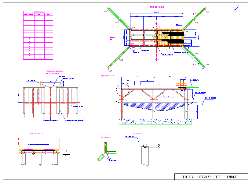
This AutoCAD drawing illustrates complete steel bridge structural details prepared for professional engineering and construction use. The drawing set includes a detailed plan view, longitudinal section, and multiple cross sections clearly labeled as typical sections. Deck layout with steel girders, transverse bracing members, and load distribution elements is shown with accurate spacing and alignment. Pile foundation details indicate vertical steel piles embedded into the ground, supporting the deck system with defined pile spacing and depth references. Connection details between girders, deck plates, and support elements are clearly marked, ensuring proper understanding of load transfer and structural behavior.
The steel bridge structural AutoCAD drawing is suitable for civil engineers, bridge designers, and infrastructure planners involved in road and access bridge projects.

Uploaded by:
Fernando Zapata
Tags
Ratings & Reviews
Be the first to share your experience with this product. Your review helps others make better decisions!