Bridge Building Floor Plan Elevation and Section CAD Drawing Layout
Tags
Ratings & Reviews
Be the first to share your experience with this product. Your review helps others make better decisions!
Description
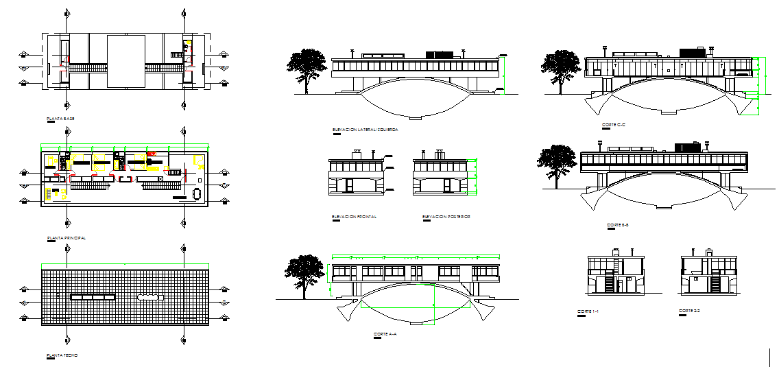
This AutoCAD DWG file presents detailed bridge building floor plan, elevation, and section drawings as shown in the uploaded image. The drawing set includes a base floor plan, a main floor layout, a roof plan, a front elevation, a rear elevation, and multiple sectional views. Internal room arrangements, corridor alignment, staircase placement, service areas, and circulation zones are clearly defined with accurate wall thickness and dimensional references. Structural supports, bridge span alignment, and deck positioning are properly represented for construction planning.
The sectional and elevation drawings illustrate floor-to-floor heights, slab levels, foundation connections, and arch support structure below the building. Roof slope design, façade composition, window placement, and balcony detailing are also visible in the elevations. Level markers, centerline references, and measurement annotations are included for technical accuracy. All drawings are prepared in standard architectural scale with professional drafting conventions. This CAD file supports bridge-based building planning, infrastructure design coordination, and construction documentation, matching the exact visual information provided in the uploaded drawing image.

Uploaded by:
john kelly
Tags
Ratings & Reviews
Be the first to share your experience with this product. Your review helps others make better decisions!