Bridge Deck and Beam Framing Structural CAD Drawing Layout Plan
Tags
Ratings & Reviews
Be the first to share your experience with this product. Your review helps others make better decisions!
Description
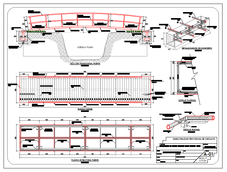
This AutoCAD DWG file presents detailed concrete bridge structural layout drawings as shown in the uploaded image. The drawing set includes a bridge plan view, a transverse section, a longitudinal layout, and a structural framing arrangement. Deck slab alignment, beam spacing, pier positioning, and abutment connections are clearly illustrated with accurate dimensional references. Reinforcement distribution, slab panel arrangement, and edge beam detailing are properly marked for construction planning and structural coordination.
The sectional and detail drawings explain load transfer paths, foundation seating, bearing placement, and structural joint connections. Platform fixing details, concrete reinforcement layouts, and support framing systems are represented according to standard bridge engineering practices. Level indicators, centerline references, and tolerance measurements are included for technical accuracy. All drawings are prepared in proper engineering scale with professional layering and drafting conventions. This CAD file supports bridge design development, working drawing preparation, and construction documentation, matching the exact technical information visible in the uploaded drawing image.

Uploaded by:
Neha mishra
Tags
Ratings & Reviews
Be the first to share your experience with this product. Your review helps others make better decisions!