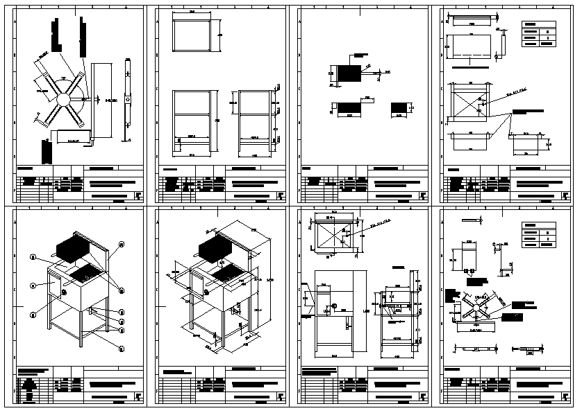
Mechanical Processing Machine Layout Drawing with Size Details
Tags
Ratings & Reviews
Be the first to share your experience with this product. Your review helps others make better decisions!
Description
This AutoCAD DWG file shows a detailed mechanical machine assembly drawing with clear front view, side view, top view, and isometric perspective. The drawing includes accurate measurements in millimeters, structural frame dimensions, base support layout, roller positioning, motor mounting area, shaft alignment, and component spacing. All main parts are properly arranged with technical detailing, making it suitable for fabrication, installation, and industrial layout planning. The file represents a complete machine structure with a working platform, support stands, rotating units, and a safety frame design.
This professional CAD drawing is useful for architects, mechanical engineers, civil engineers, and industrial designers for manufacturing reference and workshop planning. The DWG file helps in understanding machine height, width, length, clearance space, and installation requirements. With a standardized drafting format and precise dimensions, this mechanical machine layout drawing improves technical accuracy, material estimation, and project execution for industrial and construction applications.

Uploaded by:
Jafania Waxy
Tags
Ratings & Reviews
Be the first to share your experience with this product. Your review helps others make better decisions!