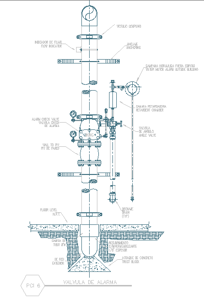
Machinery Detail CAD Drawing with Assembly Section and Dimensions
Tags
Ratings & Reviews
Be the first to share your experience with this product. Your review helps others make better decisions!
Description
This machinery detail CAD drawing is a precise AutoCAD-based design created for industrial and mechanical layout reference. The drawing illustrates detailed machinery assembly views, component alignment, base frame layout, and structural support details with clearly marked dimensions and measurement annotations. It includes plan and section views showing equipment height, base plate size, fixing bolt positions, and spacing between mechanical parts. The detailed labeling helps users understand machinery configuration, installation clearance, and functional layout required for industrial setups. Proper layering and scale settings ensure the drawing remains clear, editable, and suitable for professional documentation. Through a Cadbull subscription, users can download this machinery detail DWG file and access a wide range of industrial CAD drawings. This drawing is useful for architects, civil engineers, builders, and designers involved in factory planning, workshop layouts, and mechanical coordination. The AutoCAD machinery detail design reduces drafting effort while improving accuracy and presentation quality. Fully compatible with AutoCAD, Revit, 3ds Max, and SketchUp, this drawing supports efficient planning, equipment installation coordination, and construction-ready documentation for industrial and utility projects.

Uploaded by:
john kelly
Tags
Ratings & Reviews
Be the first to share your experience with this product. Your review helps others make better decisions!