Structural Drainage Channel CAD Drawing with Sections and Dimensions
Tags
Ratings & Reviews
Be the first to share your experience with this product. Your review helps others make better decisions!
Description
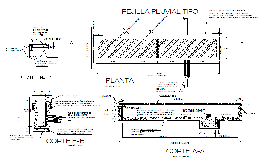
This Structure Detail CAD drawing presents a detailed drainage channel and structural slab design prepared in AutoCAD format with precise measurements. The drawing includes a clearly defined plan view showing channel length segmentation, slab width, and reinforcement layout, making it suitable for accurate construction planning. Section A and Section B are provided to explain depth, slope, concrete thickness, and pipe alignment, ensuring proper understanding of structural behavior and water flow direction. Reinforced concrete details, minimum slope values, and pipe diameter annotations support engineering-level detailing.
The drawing further illustrates material specifications such as concrete grades, reinforcement placement, and base preparation layers. Dimensional markings for widths, depths, and offsets are clearly noted to assist architects and civil engineers during execution. This Structure Detail DWG file is ideal for use in drainage systems, plinth level construction, and infrastructure-related building works where accuracy and clarity are essential. The file serves as a reliable CAD reference for professional documentation, study, and site coordination.

Uploaded by:
Jafania Waxy
Tags
Ratings & Reviews
Be the first to share your experience with this product. Your review helps others make better decisions!