Footing Slab Detail Drawing Showing Duct Passage and Concrete Layers
Tags
Ratings & Reviews
Be the first to share your experience with this product. Your review helps others make better decisions!
Description
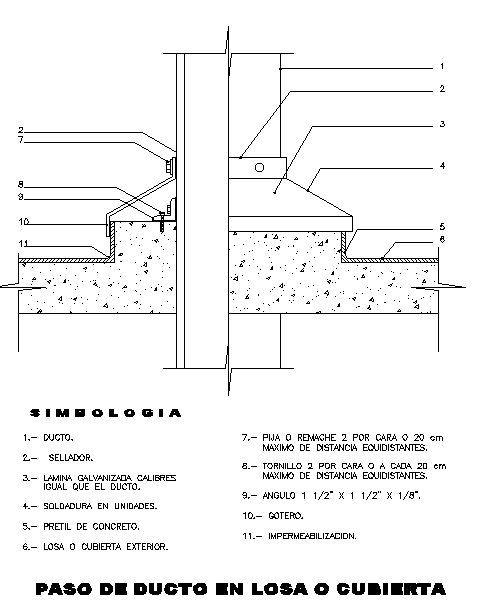
This footing slab detail drawing provides a clear sectional representation of a duct passing through a concrete slab, prepared in AutoCAD format for construction detailing. The drawing illustrates slab and footing alignment with duct placement, showing all connected construction elements in a structured manner. Key components such as galvanized duct, sealant application, welded joints, concrete curb, exterior slab or roof covering, and waterproofing layer are clearly labeled. Fixing details include rivets or fasteners placed at a maximum spacing of 20 cm, screws on each side, and metal angle supports sized at 1 1 2 inch by 1 1 2 inch by 1 8 inch. The concrete slab thickness, edge profiling, and slope for water discharge are clearly shown to support correct execution.
This footing slab detail design drawing is useful for architects, civil engineers, builders, and construction professionals involved in building services coordination and slab detailing. The AutoCAD DWG file allows easy modification and integration with architectural and structural drawings using AutoCAD, Revit, 3ds Max, or SketchUp. The clear sectional layout supports accurate installation of ducts through slabs while maintaining waterproofing integrity. This drawing helps reduce site errors and supports proper coordination between structural and mechanical elements, making it a valuable CAD resource available through a Cadbull subscription.

Uploaded by:
Jafania Waxy
Tags
Ratings & Reviews
Be the first to share your experience with this product. Your review helps others make better decisions!