Bridge Structure Design Drawing Plan Elevation Section Layout
Tags
Ratings & Reviews
Be the first to share your experience with this product. Your review helps others make better decisions!
Description
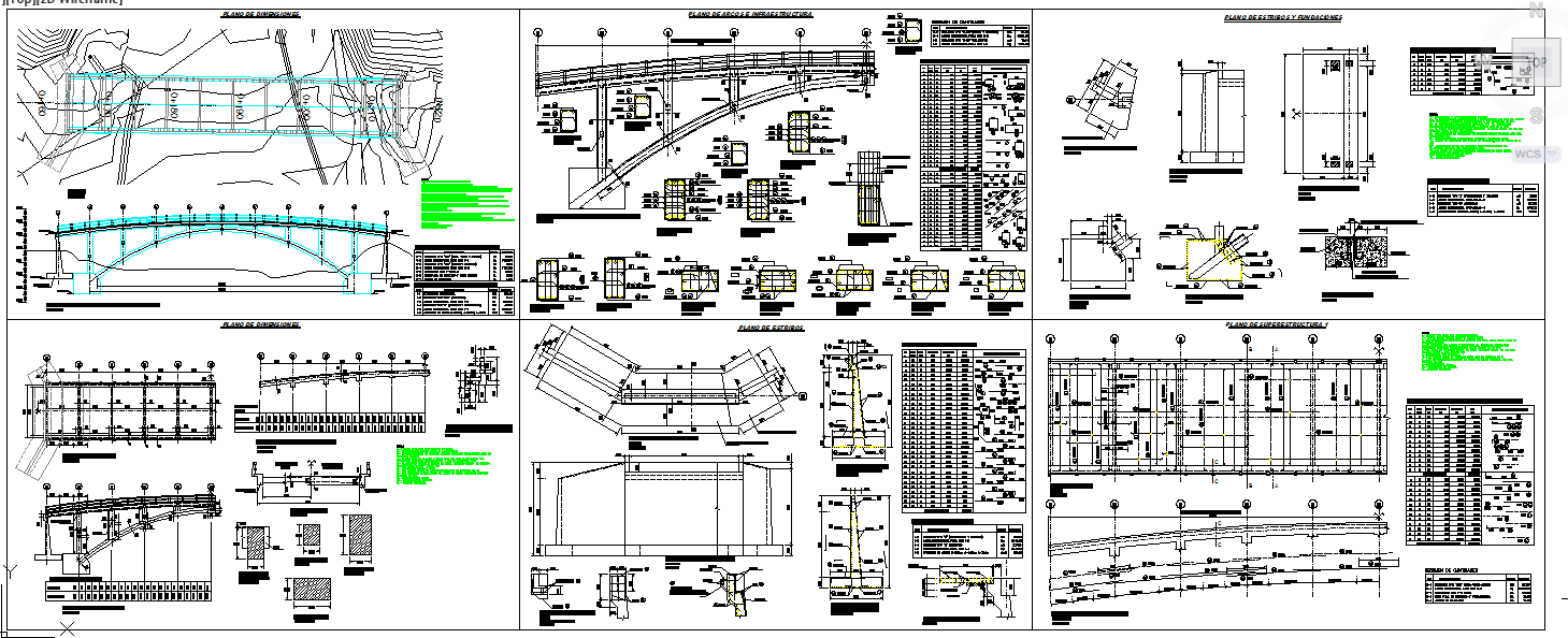
Download the Bridge Structure Design Drawing Plan Elevation Section Layout in AutoCAD DWG format, prepared with complete structural and dimensional information for professional bridge construction projects. This drawing presents a detailed site layout, a curved and straight alignment plan, a longitudinal profile, a deck slab arrangement, pier and abutment positioning, bearing layout, and foundation configuration. It includes superstructure and substructure drawings with typical span lengths of 20m to 35m, deck width of approximately 7.5m to 10.0m, pier spacing, girder placement, reinforcement detailing, drainage system, and approach slab connection. All dimensions, centerline references, and elevation levels are clearly marked for accurate field execution and technical review.
The Bridge Structure Design Drawing Plan Elevation Section Layout also contains sectional views, footing reinforcement schedules, column detailing, expansion joint layouts, parapet wall configuration, and construction specifications. Bar bending schedules, material quantity tables, and structural notes support precise estimation and quality control.

Uploaded by:
Eiz Luna
Tags
Ratings & Reviews
Be the first to share your experience with this product. Your review helps others make better decisions!