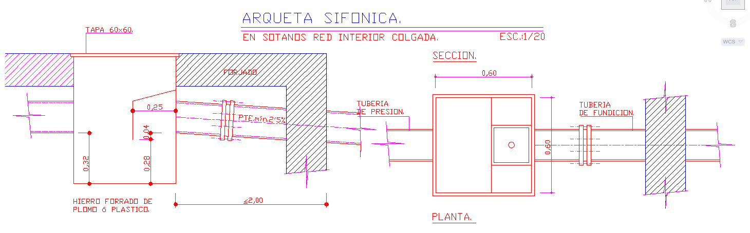
Siphonic Chamber DWG with Pressure Pipes and Concrete Structure
Tags
Ratings & Reviews
Be the first to share your experience with this product. Your review helps others make better decisions!
Description
Enhance your plumbing and architectural projects with this detailed Siphonic Chamber DWG file. This AutoCAD drawing illustrates a siphonic chamber installed in the basement interiors with precise measurements and structural details. The drawing includes a reinforced concrete chamber measuring 0.32 m by 0.28 m, with a 60x60 cm cover, and detailed annotations for pressure pipes and cast-in pipes. The chamber is designed with a minimum slope of 2.5% to ensure efficient flow, and an iron lining covered with lead or plastic is shown for structural reinforcement. Architects, civil engineers, and builders can use this DWG file to accurately plan and install siphonic chambers for drainage and water management systems.

Uploaded by:
Liam White
Tags
Ratings & Reviews
Be the first to share your experience with this product. Your review helps others make better decisions!