Electrical Circuit Building Layout AutoCAD Drawing for Projects
Tags
Ratings & Reviews
Be the first to share your experience with this product. Your review helps others make better decisions!
Description
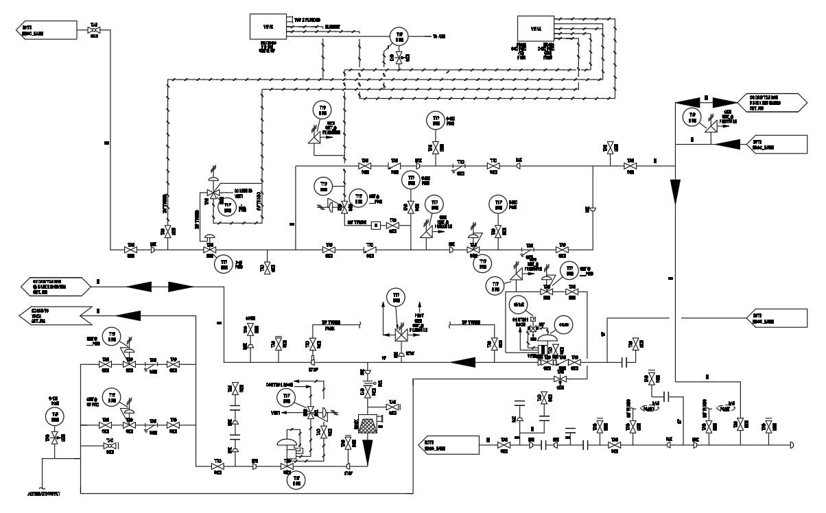
This AutoCAD DWG file presents a detailed electrical circuit building layout prepared for professional building and industrial projects. The 2D CAD drawing clearly illustrates the complete electrical power supply chain, including circuit routing, control symbols, connection points, and standardized electrical notations. Line hops are accurately used wherever conductors cross, ensuring clarity and avoiding misinterpretation during execution. The layout follows structured electrical drafting practices, making it suitable for technical coordination and construction-level documentation.
The drawing is ideal for architects, civil engineers, electrical engineers, and MEP consultants who require precise electrical circuit layouts for planning and installation. It supports integration with AutoCAD-based workflows and can be referenced for circuit coordination, load distribution planning, and system understanding. All components are logically arranged to represent a real-world electrical network configuration, helping professionals reduce design conflicts and improve site execution accuracy. This AutoCAD DWG file is available through subscription access on cadbull.com and is suitable for use in building design, electrical detailing, and project documentation workflows.
Uploaded by:
Komal
Tags
Ratings & Reviews
Be the first to share your experience with this product. Your review helps others make better decisions!