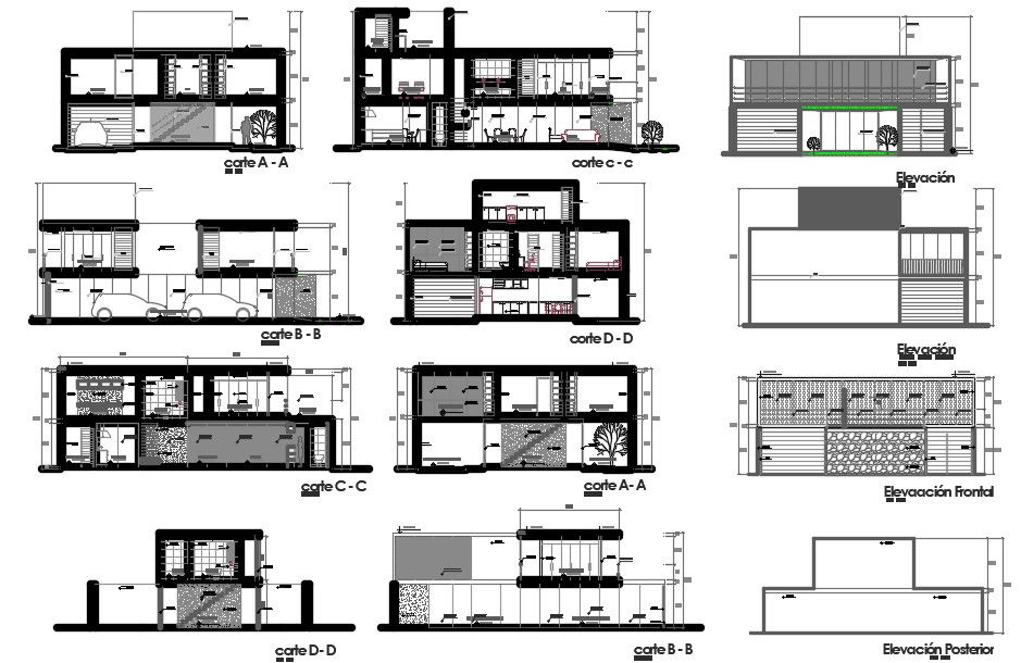
Multi Level Building Section and Elevation Layout Drawing CAD
Tags
Ratings & Reviews
Be the first to share your experience with this product. Your review helps others make better decisions!
Description
This AutoCAD DWG file presents a detailed multi-level building drawing with multiple sectional cuts and elevation views prepared for construction understanding. The drawing supports Column Details Drawing by clearly showing column positions aligned vertically through different section cuts, helping in understanding structural continuity and load flow. Column locations are coordinated with walls, slabs, and internal spaces to maintain proper structural balance. The drawing also includes Beam and Lintel representation, where horizontal members are shown above openings and along floor levels, explaining how loads are distributed between columns across the building width. Wall thicknesses, slab edges, and reference markers are clearly drafted for technical clarity.
The drawing further reflects Staircase Sections through clearly visible sectional cuts that explain stair rise, tread alignment, landing positions, and vertical movement between floors. Staircase placement is consistent across sections to support smooth circulation planning. In addition, Footing Detail reference is indicated through column base alignment and foundation level relationships visible in the sectional views, helping in understanding load transfer from the structure to the ground. Front and rear elevation views illustrate façade proportions, opening alignment, and external offsets coordinated with the sectional layout. Clean CAD line work, readable annotations, and accurate scaling make this AutoCAD DWG file suitable for understanding column placement, beam alignment, staircase section planning, and footing reference for building construction drawings.
Uploaded by:
Komal
Tags
Ratings & Reviews
Be the first to share your experience with this product. Your review helps others make better decisions!