Pressure Indicator Plan Elevation and Section Detail AutoCAD
Tags
Ratings & Reviews
Be the first to share your experience with this product. Your review helps others make better decisions!
Description
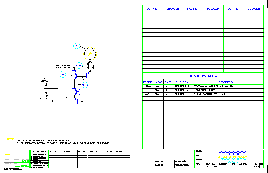
This AutoCAD DWG file provides detailed drawings of a pressure indicator, showing plan, elevation, and sectional views for precise pneumatic measurement reference. The drawing illustrates the sensing element, including the piston or diaphragm, and the rod mechanism that transmits pressure to the recording instrument. Architects, mechanical engineers, and builders can use this file to understand the installation, alignment, and operational functionality of the pressure indicator within building or industrial systems.
The DWG also includes detailed component labeling, such as valves, connectors, and measurement points for accurate assembly and operation. Builders and designers can refer to these details to ensure proper installation, calibration, and integration with piping or instrumentation systems. This professional drawing serves as a reference for planning, technical detailing, and execution of pressure indicator setups in industrial, residential, or commercial projects using AutoCAD.
Uploaded by:
viddhi chajjed
Tags
Ratings & Reviews
Be the first to share your experience with this product. Your review helps others make better decisions!