Refrigerator piping diagram and details for ceiling mounted compressor
Description
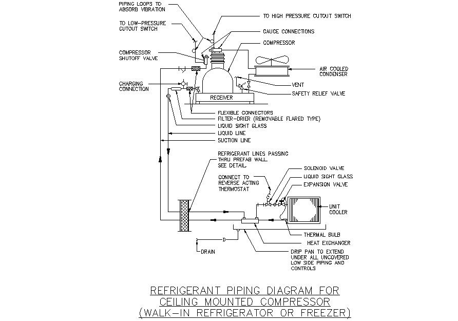
Here Refrigerator piping diagram and details for ceiling mounted compressor including vent ,safety relief valve , compressor , gauge connection , air cooled condenser high pressure cutout switch , low pressure cutout switch , piping loops to absorb vibration , compressor shutoff valve , flexible connections , filter drier , liquid sight grass , liquid line , suction line , solenoid valve , expansion valve , unit cooler , thermal bulb , heat exchange , drip plan to extend under all uncovered low side piping and controls , connect to reverse acting thermostat , charger connection , The suction line connects the evaporator to the compressor, the discharge line connects the compressor to the condenser, and the liquid line connects the condenser to the expansion device. connect the outdoor air conditioner or heat pump to the indoor evaporator coil. The larger line typically carries a cool gas and is insulated. This is commonly referred to as the suction line, but it is also called the return line or vapor line. The purpose of the lines is to keep the losses to a minimum. This is done to make sure there is enough Net Positive Suction Head available to meet the requirements of the pump. for more details of Refrigerator piping diagram and details for ceiling mounted compressor download this file.
Uploaded by:
zalak
prajapati
