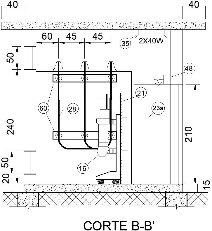
The Rectifier System details AutoCAD file, cad drawing or dwg format.
Tags
Ratings & Reviews
Be the first to share your experience with this product. Your review helps others make better decisions!
Description
The simple half-wave rectifier can be built in two electrical configurations with the diodes pointing in opposite directions, one version connects the negative terminal of the output direct to the AC supply and the other connects the positive terminal of the output direct to the AC supply. By combining both of these with separate output smoothing it is possible to get an output voltage of nearly double the peak AC input voltage. This also provides a tap in the middle, which allows use of such a circuit as a split rail power supply.A variant of this is to use two capacitors in series for the output smoothing on a bridge rectifier then place a switch between the midpoint of those capacitors and one of the AC input terminals. With the switch open, this circuit acts like a normal bridge rectifier. With the switch closed, it acts like a voltage doubling rectifier. In other words, this makes it easy to derive a voltage of roughly 320 V (±15%, approx.) DC from any 120 V or 230 V mains supply in the world, this can then be fed into a relatively simple . However, for a given desired ripple, the value of both capacitors must be twice the value of the single one required for a normal bridge rectifier; when the switch is closed each one must filter the output of a half-wave rectifier, and when the switch is open the two capacitors are connected in series with an equivalent value of half one of them. for more details of The Rectifier System download this AutoCAD file, cad drawing or dwg format
Uploaded by:
zalak prajapati
Tags
Ratings & Reviews
Be the first to share your experience with this product. Your review helps others make better decisions!