RCC Plinth And Vertical Angle Coping Section Construction Drawing
Tags
Ratings & Reviews
Be the first to share your experience with this product. Your review helps others make better decisions!
Description
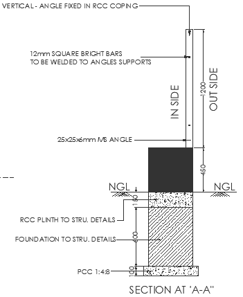
This AutoCAD drawing shows a detailed RCC plinth and vertical angle fixing section with RCC coping, prepared for accurate structural execution. The section at A A clearly illustrates the RCC plinth to structure connection, including PCC base of 1:4:8 mix, foundation depth of approximately 1000 mm, and stepped plinth construction above natural ground level. Vertical MS angles of size 25x25x6 mm are shown fixed into the RCC coping, providing structural support and edge protection. The drawing also specifies 12 mm square bright bars welded to the angle supports for secure anchorage and alignment.
The section differentiates inside and outside levels with clear NGL references and vertical height indication of around 2800 mm above the coping level. RCC plinth thickness, coping projection, angle embedment depth, and foundation layering are precisely dimensioned to support site-level coordination and construction accuracy. This DWG file is suitable for architects, civil engineers, and builders working on boundary walls, compound walls, and RCC-framed structures. Subscription access allows professionals to directly use this ready-made AutoCAD drawing to reduce detailing time, maintain dimensional clarity, and ensure consistent execution as per standard construction practices.

Uploaded by:
Liam White
Tags
Ratings & Reviews
Be the first to share your experience with this product. Your review helps others make better decisions!