Isolation Board Detail Around Column and Wall for 250 and 350 Flooring
Tags
Ratings & Reviews
Be the first to share your experience with this product. Your review helps others make better decisions!
Description
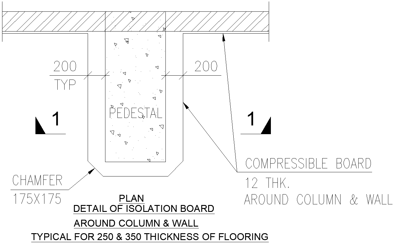
This AutoCAD drawing presents a clear plan detail of an isolation board arrangement provided around a column and wall, specifically designed for floor thicknesses of 250 mm and 350 mm. The drawing illustrates a central concrete pedestal with a chamfer size of 175 x 175 mm at the base, ensuring smooth load transfer and reduced stress concentration. A uniform clearance of 200 mm is maintained on both sides, marked as typical, to accommodate isolation detailing. A 12 mm thick compressible board is shown continuously around the column and wall interface, allowing controlled movement between structural and non-structural elements. All dimensions, annotations, and sectional indicators are clearly marked for accurate interpretation during execution.
This DWG file is highly useful for architects, civil engineers, and construction professionals working on residential, commercial, or industrial flooring systems. The isolation board detail helps in minimizing vibration transfer, thermal bridging, and unwanted stress due to differential movement. The plan clearly defines pedestal positioning, flooring thickness references, and compressible board placement, making it suitable for direct construction use and authority submissions. Downloading this AutoCAD drawing through a subscription saves drafting time, improves coordination accuracy, and ensures compliance with standard construction detailing practices while maintaining precision at column and wall junctions.

Uploaded by:
Liam White
Tags
Ratings & Reviews
Be the first to share your experience with this product. Your review helps others make better decisions!