Substation Reinforced Earth Retaining Wall Profile Drawing DWG
Description
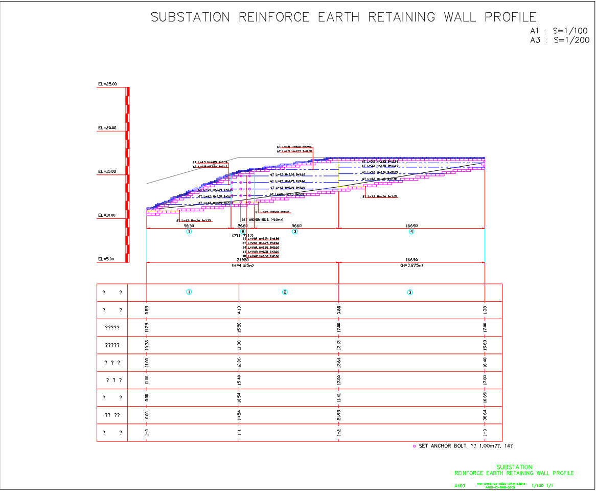
This AutoCAD DWG engineering drawing illustrates a reinforced earth retaining wall profile designed for a substation project, developed under KECC structural standards. The plan showcases wall height variations (H=0.50m–5.00m), lengths (L=3.2m–4.5m), and base widths (B=2.05m–16.69m) with A400 reinforcement details and anchor bolt spacing of 1.00m.
The retaining wall profile (A1: S=1/100 and A3: S=1/200) provides top and bottom elevation marks (EL=5.00 to EL=25.00) for field implementation. Key design parameters include section alignment, slope grades, additional distances, and grid interference zones (??? ????), ensuring precision in construction.
This drawing is essential for civil and structural engineers managing substation site development, slope stabilisation, and foundation protection. It provides reinforcement placement, wall joint references, and anchor installation guides for stability and load resistance.
File Type:
DWG
File Size:
130 KB
Category::
Construction
Sub Category::
Construction Detail Drawings
type:
Free
Uploaded by:
apurva
munet
