Substation Reinforced Earth Retaining Wall Profile With Levels
Ratings & Reviews
Be the first to share your experience with this product. Your review helps others make better decisions!
Description
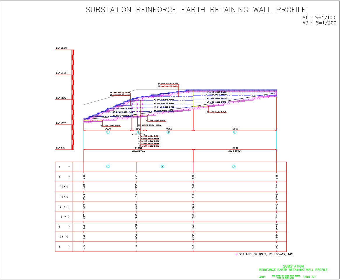
This AutoCAD DWG drawing shows a detailed reinforced earth retaining wall profile designed specifically for a substation project. The profile illustrates wall height variations ranging from 0.50 m to 5.00 m with clear sectional alignment and stepped slope geometry. Lengths between sections vary approximately from 3.20 m to 4.50 m, while base widths are defined from 2.05 m up to 16.69 m, ensuring structural stability across different elevations. Top and bottom levels are clearly marked from EL 5.00 to EL 25.00, allowing accurate site setting out and excavation control. Reinforcement specifications using A400 grade steel are indicated along with anchor bolt spacing fixed at 1.00 m for load transfer and soil reinforcement.
The drawing is prepared at scales A1 1:100 and A3 1:200 and includes reinforcement layers, wall batter slope grades, and anchor belt positioning for construction clarity. Section references joint locations and reinforcement placement zones are shown to support substation foundation protection and slope stabilisation works. This DWG file is useful for civil engineers, structural engineers, and contractors involved in substation infrastructure development requiring precise retaining wall profile details for execution and compliance with engineering standards.
File Type:
DWG
File Size:
130 KB
Category::
Construction
Sub Category::
Construction Detail Drawings
type:
Free
Tags
Uploaded by:
apurva
munet
Ratings & Reviews
Be the first to share your experience with this product. Your review helps others make better decisions!