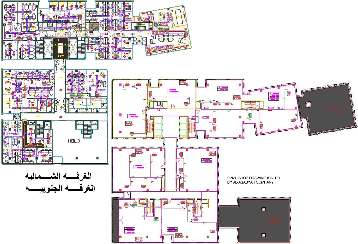
Corporate Office VRF Air Conditioning Layout Plan With Ducting
Ratings & Reviews
Be the first to share your experience with this product. Your review helps others make better decisions!
Description
This AutoCAD DWG drawing presents a detailed VRF air conditioning layout designed for a corporate office building with multi-zone cooling requirements. The plan illustrates the complete HVAC arrangement, including outdoor VRF units GMV ND224PH A T with 6.4 TR 22.4 kW capacity and GMV ND160PHS B T with 4.57 TR 16.0 kW capacity connected through Y branch joints and insulated copper refrigerant piping. Indoor VRF units ranging from 3.2 TR to 6.4 TR are distributed across meeting rooms, open office areas, and executive cabins to maintain balanced cooling and energy efficiency. The total connected F U load of 61.5 kW is clearly coordinated for system performance. This DWG file is suitable for architects, HVAC consultants, MEP engineers, and contractors requiring a precise VRF air conditioning layout for corporate office projects.
Tags
Uploaded by:
Dhara
Ratings & Reviews
Be the first to share your experience with this product. Your review helps others make better decisions!