Preliminary Piping Layout DWG with 2200 mm Section and Flange Details

Ratings & Reviews
Be the first to share your experience with this product. Your review helps others make better decisions!
Description
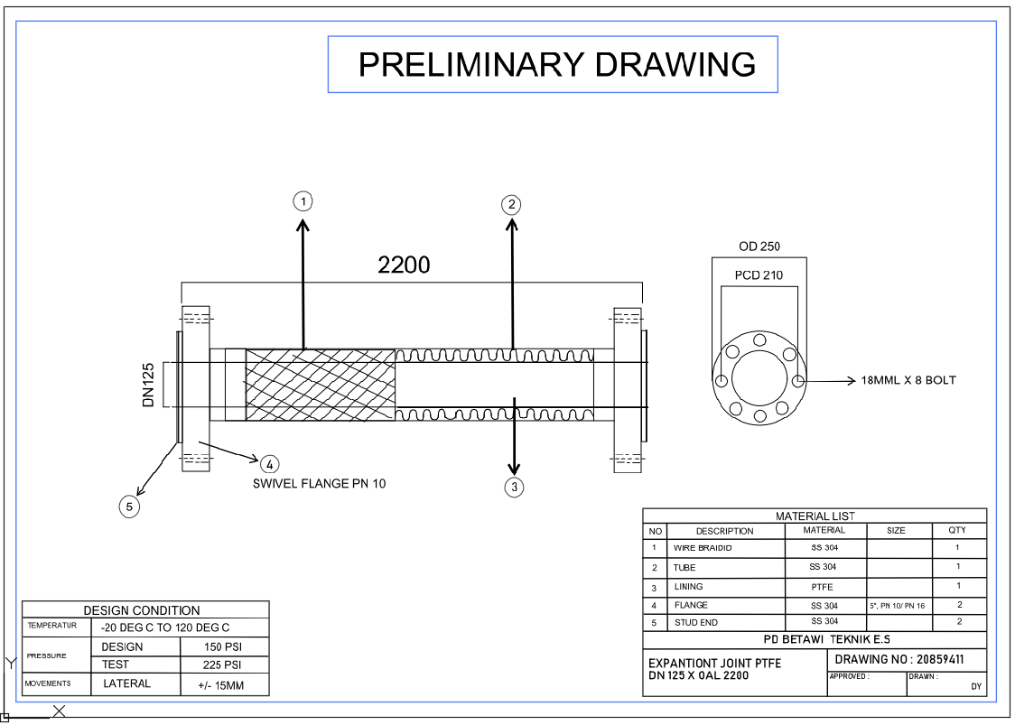
This AutoCAD DWG file presents a preliminary piping layout, showing a detailed 2200 mm pipe section with sectional hatching, internal layering, and joint indicators as illustrated on page 1 of the drawing. The drawing displays tagged components such as item 1, representing a directional connection reference, and item 4, marking the PN10 swivel flange installation point. The cutaway view of the pipe reveals the internal structure, wall thickness representation, and insulation or lining pattern, allowing engineers to evaluate early routing and connection feasibility. These features make the drawing valuable for pre-construction planning, material selection, and alignment verification.
Additional notations in the layout support coordination between mechanical services, identifying the flange interface and pipe length requirements. The “PRELIMINARY” header indicates that this drawing serves as an initial engineering reference before detailed fabrication is issued. The straightforward linework and proportional scaling help architects, civil engineers, MEP designers, and contractors integrate this piping layout into larger system drawings. This DWG is ideal for those requiring an accurate piping layout DWG for early-stage design, routing evaluation, and technical review during schematic development.
Tags
Uploaded by:
Liam
White
Ratings & Reviews
Be the first to share your experience with this product. Your review helps others make better decisions!