Commercial Drainage System Details DWG with 300 mm Pipe Layout

Ratings & Reviews
Be the first to share your experience with this product. Your review helps others make better decisions!
Description
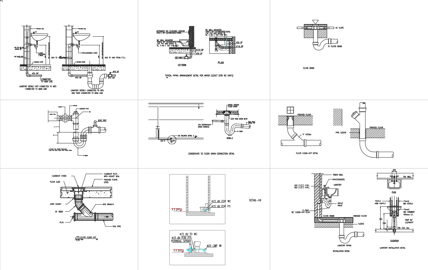
This AutoCAD DWG file illustrates a comprehensive commercial drainage system layout developed to support accurate plumbing and wastewater planning. The drawing presents detailed ground-floor drainage arrangements with clear plan views and sectional details for sanitary fixtures. It includes precise pipe routing using standard diameters such as 100 mm, 200 mm, and 300 mm to ensure efficient flow and proper system performance. Floor drain connections, gully traps, cleanouts, vent pipes, and slab penetration details are clearly marked with correct slopes and offsets. Each element is labeled with technical clarity, allowing professionals to easily interpret installation requirements and coordinate drainage systems within commercial building layouts.
The drawing further provides enlarged sectional views of floor drains, pipe sleeves, concrete floor connections, and wall penetrations. Vertical and horizontal junctions are shown with accurate alignment, levels, and spacing to reduce execution errors during construction. Inspection chambers, fixture connections, and vent terminations are detailed to support long-term system reliability and maintenance access. Standardized symbols, consistent scales, and well-defined annotations enhance readability for architects, civil engineers, interior designers, builders, and MEP consultants. This DWG file serves as a reliable technical reference for designing, reviewing, and executing commercial drainage systems with improved coordination, accuracy, and construction efficiency.
Tags
Uploaded by:
Liam
White
Ratings & Reviews
Be the first to share your experience with this product. Your review helps others make better decisions!