Existing and New Building Extension Structural Details DWG Plan
Tags
Ratings & Reviews
Be the first to share your experience with this product. Your review helps others make better decisions!
Description
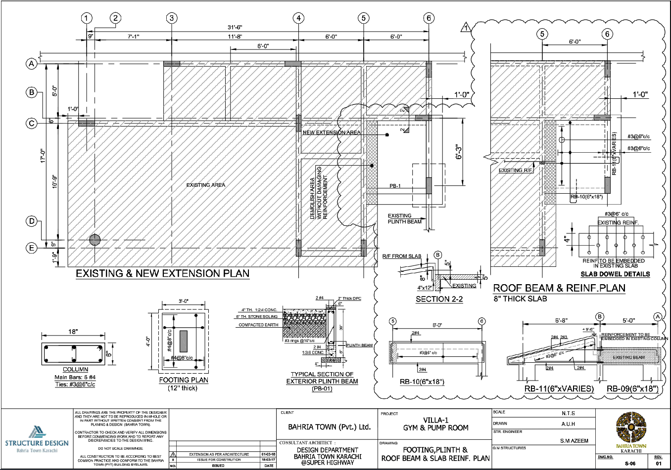
This AutoCAD DWG file provides detailed structural drawings for an existing building with a new extension layout prepared for execution level construction planning. The drawing includes an existing and new extension plan clearly differentiating the existing area, the new extension area, and the demolition zones with precise dimensional references. Structural details cover footing plans with 12-inch thick footing sizes, column reinforcement layouts, plinth beam details, and roof beam and slab reinforcement plans. Typical sections illustrate exterior plinth beam construction with 6-inch thick stone soling, compacted earth layers, concrete mixes, and damp proof course thickness. Reinforcement specifications include bar sizes, spacing such as #3 and #4 bars, c c distances, ties, and ring spacing for columns and beams. All dimensions are provided in imperial units to ensure accuracy during site execution.
The drawing also includes sectional views explaining reinforcement embedding into existing columns, roof beam sizes such as 6-inch by 18-inch beams, slab thickness references, and plinth beam configurations. Existing structural elements are coordinated with new construction to maintain continuity without damaging reinforcement. Notes, legends, and annotations ensure a clear understanding of the construction sequence and structural intent. This DWG file is suitable for architects, civil engineers, builders, and structural designers who require accurate extension planning, footing detailing, and reinforced concrete coordination for residential or utility structures, and can be effectively coordinated with detailed second-floor architectural plan drawings to ensure alignment between structural extensions and upper-level layout planning.

Uploaded by:
Neha mishra
Tags
Ratings & Reviews
Be the first to share your experience with this product. Your review helps others make better decisions!