DN 125 PTFE Expansion Joint Drawing with OAL 2200 and PN10 Flange

Ratings & Reviews
Be the first to share your experience with this product. Your review helps others make better decisions!
Description
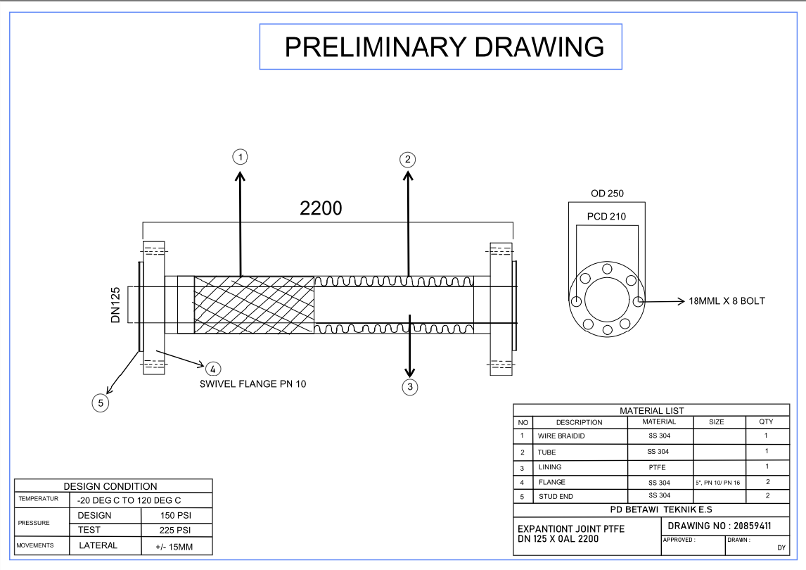
This AutoCAD drawing presents a preliminary mechanical layout of a PTFE expansion joint used in piping systems. The drawing clearly illustrates the overall assembly length of 2200 mm, DN 125 pipe size, internal lining, wire braided section, and external tube configuration. Flange details such as swivel flange PN 10, stud end arrangement, bolt hole layout, and pitch circle diameter are precisely marked for fabrication accuracy. Design conditions, including temperature range, design pressure, test pressure, and allowable lateral movement, are specified to guide engineering applications. Such drawings are commonly prepared within Mechanical Engineering documentation to support piping flexibility and vibration control.
The sheet also includes a detailed material list specifying SS 304 components, PTFE lining, flange quantities, and bolt specifications for manufacturing reference. Side views show bolt sizing and fixing methodology, while notes clarify installation tolerances and operational limits. Dimensional annotations help ensure compatibility with connected piping and equipment. These expansion joint drawings are essential in Mechanical and Machinery systems where thermal expansion, movement absorption, and stress reduction are required. The drawing further supports coordination during fabrication and installation under Construction workflows and serves as a reference detail within Other Cad Blocks documentation for industrial piping layouts.
File Type:
DWG
File Size:
183 KB
Category::
Mechanical and Machinery
Sub Category::
Mechanical Engineering
type:
Gold
Tags
Uploaded by:
Neha
mishra
Ratings & Reviews
Be the first to share your experience with this product. Your review helps others make better decisions!