Residential Heating Ventilation Ground Floor Layout AutoCAD Drawing
Tags
Ratings & Reviews
Be the first to share your experience with this product. Your review helps others make better decisions!
Description
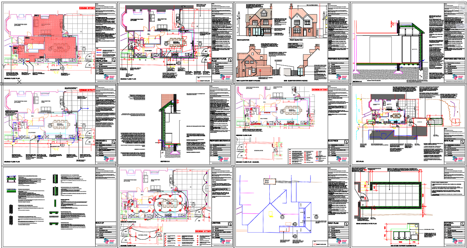
This AutoCAD DWG file presents a comprehensive residential heating and ventilation ground floor layout prepared at a scale of 1:50, suitable for tender and construction documentation. The drawing clearly illustrates the spatial planning of the kitchen and dining area, rear reception room, hallway, WC, and utility room, with precise internal dimensions such as 6000 mm reception width, 2000 mm hallway zone, and detailed service clearances. Water-fed underfloor heating zones are accurately marked for each functional area, including Zone 1 for the kitchen and rear reception, Zone 2 for the utility room, Zone 3 for the WC, and Zone 4 for hallway areas. The layout includes manifold positioning, pipe routing, radiator notes for upper floors, and electrical underfloor heating provisions for bathroom zones.
The drawing also defines mechanical ventilation specifications compliant with building regulations, including kitchen extract rates of 30 L per second adjacent to the hob or 60 L per second elsewhere, utility room ventilation at 30 L per second, and bathroom extract at 15 L per second, all ducted externally. Additional details cover wall-mounted extract fan locations, reuse of existing vent holes, appliance placements, drainage alignment, and boundary references. This DWG file is highly valuable for architects, civil engineers, MEP consultants, and interior designers seeking accurate residential heating and ventilation coordination for professional project execution.

Uploaded by:
Neha mishra
Tags
Ratings & Reviews
Be the first to share your experience with this product. Your review helps others make better decisions!