Residential Electrical Layout Ground Floor With Dimensions AutoCAD DWG

Ratings & Reviews
Be the first to share your experience with this product. Your review helps others make better decisions!
Description
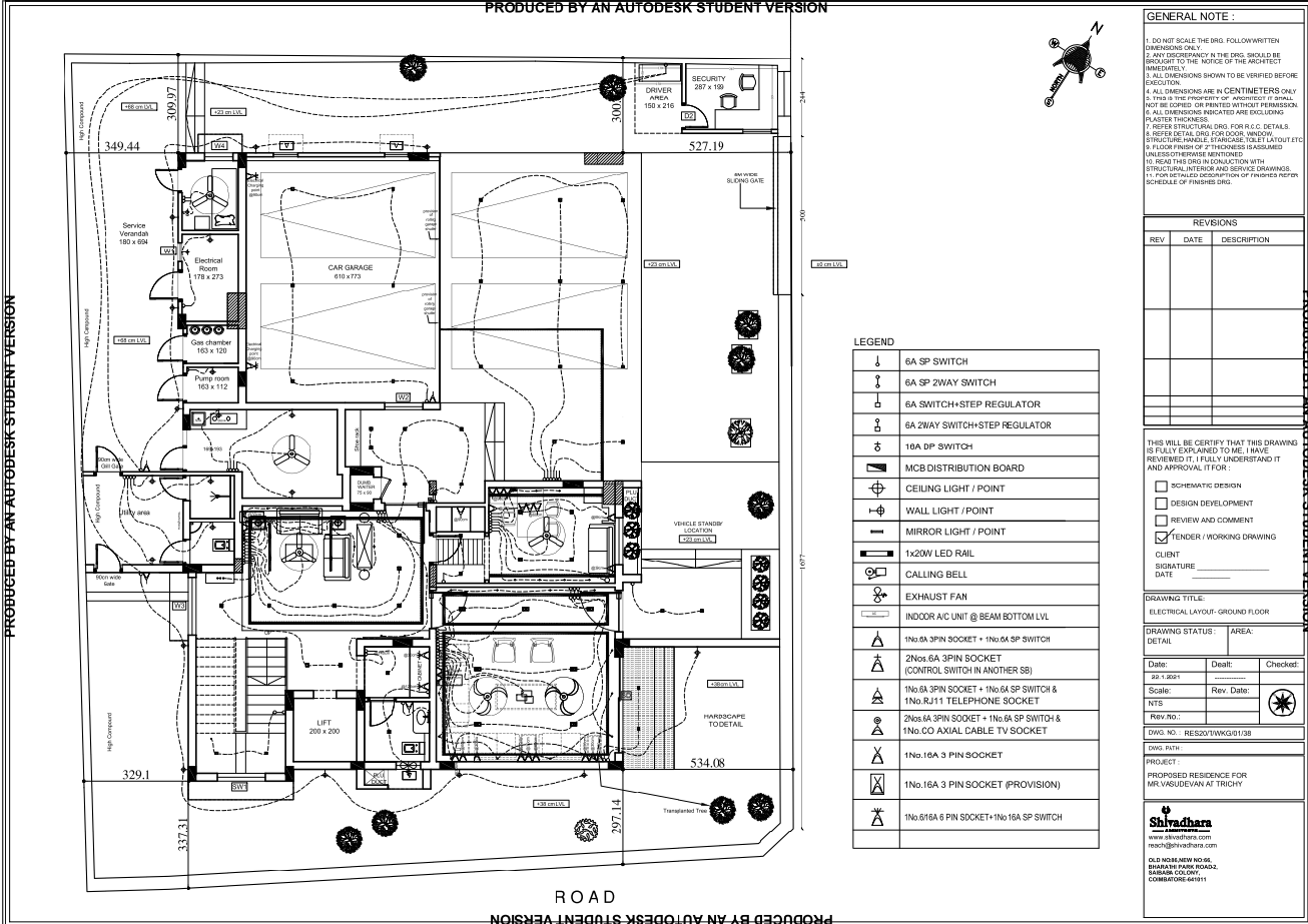
This AutoCAD DWG drawing presents a detailed residential ground floor electrical layout showing lighting points, switch positions, socket outlets, and power distribution planning. The drawing clearly illustrates ceiling light points, wall light locations, exhaust fan placement, calling bell points, and mirror light arrangements as marked in the legend. Electrical routing paths are indicated for safe and organized wiring flow across functional areas such as the car garage, utility space, living zones, bedrooms, and service areas. Level markings and spacing dimensions are included to support correct on-site execution and coordination with architectural layouts.
The plan also highlights electrical safety and functionality through the placement of distribution boards, power sockets, charging points, and control switches. Dedicated provisions for indoor AC units, exhaust systems, and lighting circuits help ensure efficient electrical load management. This electrical drawing is suitable for residential construction projects where accurate wiring coordination is required alongside architectural and interior layouts. Architects, electrical consultants, and site engineers can use this DWG file to review electrical planning, verify point locations, and align installation work with design intent for ground-floor residential buildings.
Tags
Uploaded by:
Neha
mishra
Ratings & Reviews
Be the first to share your experience with this product. Your review helps others make better decisions!