Structural Column Footing Foundation Drawing With M20 Fe500 Details
Tags
Ratings & Reviews
Be the first to share your experience with this product. Your review helps others make better decisions!
Description
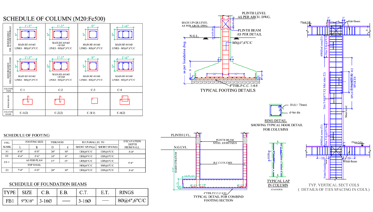
This AutoCAD DWG file presents a detailed structural drawing of column footing and foundation beam design prepared for a ground plus two-storey building. The drawing includes a complete schedule of columns using M20 concrete with Fe500 reinforcement, showing column sizes such as nine inches by nine inches and one foot three inches by nine inches with main reinforcement bars of sixteen millimeters and links of eight millimeters at specified spacing.
The footing schedule defines footing sizes, including six feet by six feet and seven feet by six feet, with thicknesses up to twenty inches and an excavation depth of five feet below natural ground level. Typical footing sections show four-inch-thick PCC in 1 ratio 4 ratio 8 mix, hard strata placement, plinth beam levels, RCC column connections, lap length details, hook details, and vertical section reinforcement zoning. Foundation beam details specify nine-inch by eighteen-inch beams with three sixteen-millimeter bars and eight-millimeter rings at four to six inches center to center. All dimensions are in feet and inches and follow IS codes, including IS 456 and IS 13920. This structural column footing drawing is suitable for execution level construction reference and professional civil engineering documentation.

Uploaded by:
Umar Mehmood
Tags
Ratings & Reviews
Be the first to share your experience with this product. Your review helps others make better decisions!