Commercial Building Architectural Elevation Drawing With Level Details
Tags
Ratings & Reviews
Be the first to share your experience with this product. Your review helps others make better decisions!
Description
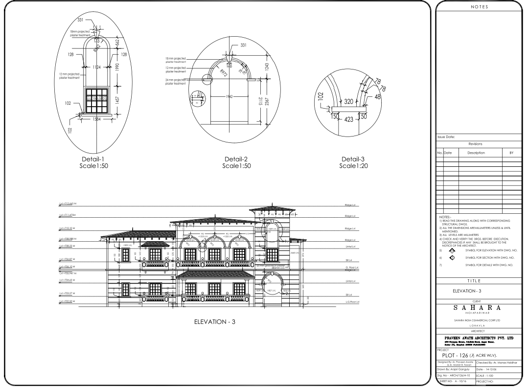
This AutoCAD DWG file features a commercial building architectural elevation drawing developed with precise vertical control and façade detailing. The elevation illustrates clearly defined level markers, including ground floor level, sill level, lintel level, ridge level, and intermediate reference heights, all measured in millimeters for execution accuracy. Height annotations such as +702.50, +704.65, +706.87, +708.25, +710.10, and +712.665 are systematically aligned across the elevation to maintain proportional façade composition. The drawing highlights arched openings, balcony projections, parapet alignment, and roof profile transitions, supporting elevation coordination for commercial structures. Exterior surface treatment is detailed using 25 mm plaster grooves at 485 mm center-to-center spacing, improving clarity for façade finishes and site implementation.
The drawing further includes enlarged architectural details for execution reference, such as Detail 1 and Detail 2 at scale 1:50 and Detail 3 at scale 1:20. These sections explain curved window arches, wall thicknesses of 102 mm, projection depths, sill offsets, and plaster treatments of 12 mm, 18 mm, and 24 mm. Radius dimensions, including R972 and R56.2, are accurately marked to guide curved façade elements. All dimensions follow millimeter standards and are intended to be read alongside corresponding structural drawings. This elevation DWG supports architects, civil engineers, interior designers, builders, and BIM professionals using AutoCAD, 3D Max, Revit, and SketchUp for professional commercial elevation planning and documentation, and follows architectural detailing standards similar to high-end residential apartment CAD layouts, such as 3 BHK luxury apartment plans that emphasize façade proportion, elevation detailing, and execution-level coordination.

Uploaded by:
Liam White
Tags
Ratings & Reviews
Be the first to share your experience with this product. Your review helps others make better decisions!