Mechanical HVAC Control Diagrams for Air Handling and Ventilation

Ratings & Reviews
Be the first to share your experience with this product. Your review helps others make better decisions!
Description
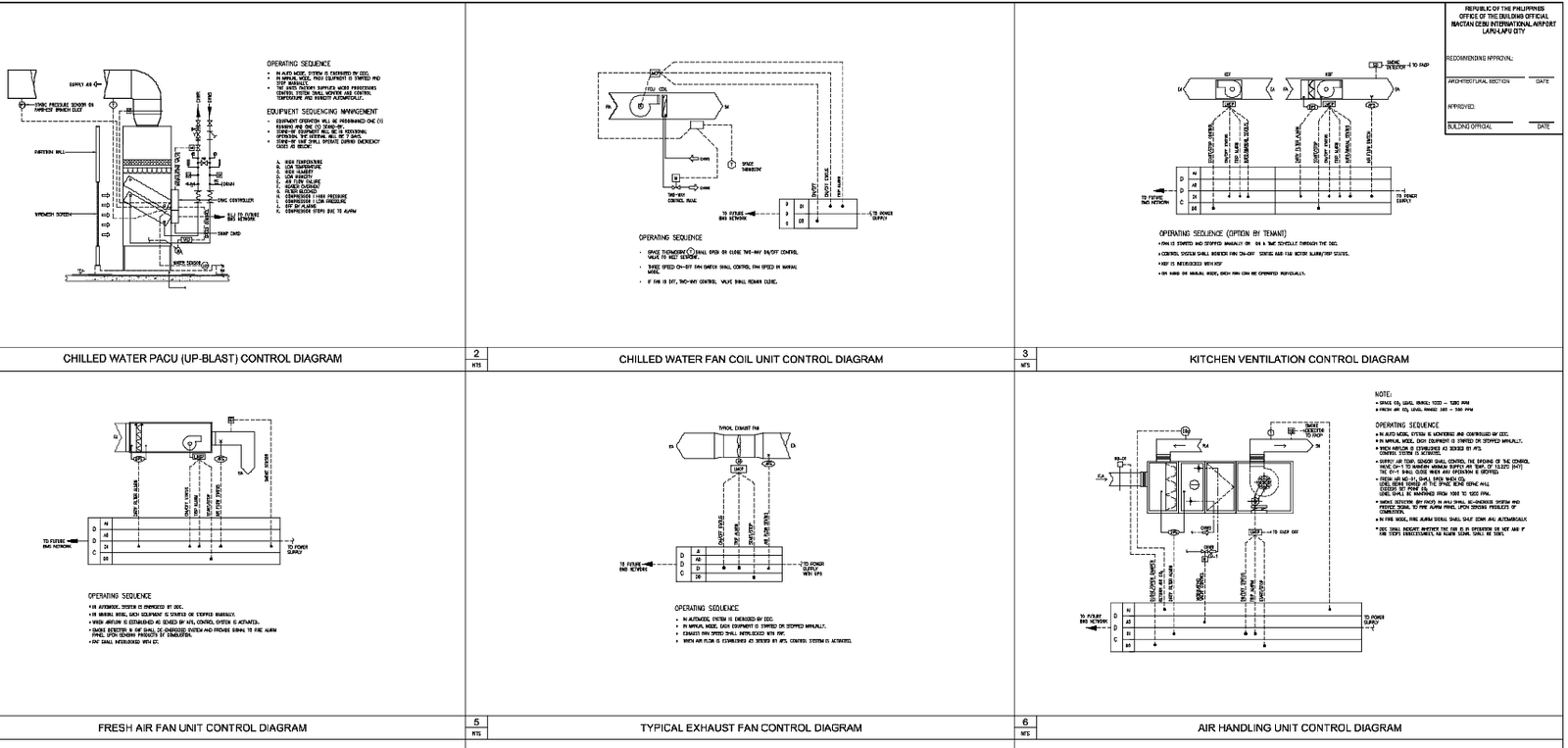
This mechanical drawing presents a complete set of HVAC control diagrams prepared for coordinated building services design. The layout includes chilled water PACU control diagrams, fan coil unit control logic, air handling unit control systems, fresh air fan wiring diagrams, exhaust fan control arrangements, and kitchen ventilation control schematics. Each diagram clearly illustrates control wiring paths, sensor connections, power supply routing, interlocking sequences, and operational logic required for smooth HVAC functioning. Control panels, thermostats, valves, dampers, and motorized components are shown with standardized symbols to support accurate mechanical coordination and installation planning.
The drawing also explains system operation sequences for each HVAC component, including automatic start stop functions, safety interlocks, alarm connections, and temperature control mechanisms. Clear labeling of terminals, controllers, actuators, and equipment interfaces ensures ease of interpretation for mechanical engineers, consultants, and contractors. These HVAC mechanical control diagrams are suitable for commercial buildings, institutional projects, and large-scale developments where precise ventilation and air conditioning control are required. The detailed representation supports efficient coordination between mechanical, electrical, and automation systems during execution and commissioning stages with reference to pump room electrical layout CAD drawings that demonstrate similar standards of control coordination, wiring clarity, system interlocking, and construction-ready MEP documentation.
File Type:
DWG
File Size:
414 KB
Category::
Mechanical and Machinery
Sub Category::
Mechanical Engineering
type:
Gold
Tags
Uploaded by:
Umar
Mehmood
Ratings & Reviews
Be the first to share your experience with this product. Your review helps others make better decisions!