AutoCAD HVAC Control Diagrams for Airport Terminal Mechanical Systems

Ratings & Reviews
Be the first to share your experience with this product. Your review helps others make better decisions!
Description
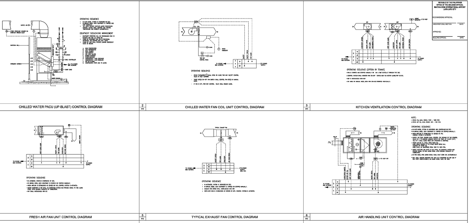
This AutoCAD DWG file contains a complete set of mechanical services control diagrams prepared for an airport terminal refurbishment project. The drawing sheet includes Chilled Water PACU Up-Blast Control Diagram, Chilled Water Fan Coil Unit Control Diagram, Kitchen Ventilation Control Diagram, Fresh Air Fan Unit Control Diagram, Typical Exhaust Fan Control Diagram, and Air Handling Unit Control Diagram. Each diagram clearly illustrates equipment connections, sensors, actuators, control panels, wiring paths, and operating sequences for HVAC and ventilation systems. The layouts explain how fans, PACUs, FCUs, AHUs, and exhaust units interact within a centralized control network, making it ideal for MEP consultants, mechanical engineers, and BIM professionals. This professional AutoCAD DWG file supports accurate system coordination, tender documentation, and Revit or 3D modeling workflows for large commercial and public buildings such as airports, malls, and terminals. With reference to residential house plan drawings that demonstrate coordinated ground and first-floor planning standards commonly prepared in AutoCAD DWG format.
Tags
Uploaded by:
Liam
White
Ratings & Reviews
Be the first to share your experience with this product. Your review helps others make better decisions!