Penthouse Roof Framing And Elevator Machine Room Plan AutoCAD

Ratings & Reviews
Be the first to share your experience with this product. Your review helps others make better decisions!
Description
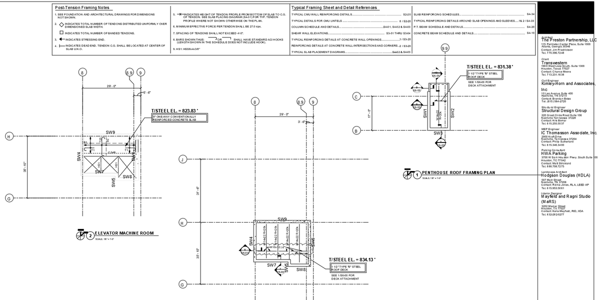
This AutoCAD DWG file presents a detailed penthouse roof framing plan and elevator machine room structural layout designed for high-rise building construction. The drawing includes post-tension slab framing notes, steel beam placement, and slab reinforcement coordination with clearly marked grid dimensions such as 29 ft 0 i,n 30 ft 10 in, and 31 ft 6 in. Structural steel members like W14x22 beams witha reaction capacity of 20 kips, and W10x12 sections are shown with precise alignment. The plan identifies the top of steel levels at 823.83 f,t 831.38 ft, and 834.13 ft, ensuring accurate elevation control. Roof construction details include a 1.5-inch type B steel roof deck and an 8-inch one-way conventionally reinforced concrete slab. The elevator machine room layout shows shear wall tags SW4, SW7, SW8, and SW9 with slab opening coordination and deck attachment references. Post tension tendon spacing is limited to 4 ft 0 in, and a minimum effective force of 27.0 kips is specified for structural safety.
File Type:
DWG
File Size:
133 KB
Category::
Mechanical and Machinery
Sub Category::
Elevator Details
type:
Gold
Tags
Uploaded by:
Umar
Mehmood
Ratings & Reviews
Be the first to share your experience with this product. Your review helps others make better decisions!