Lift Pit Detail DWG 1530x1930 Section A A B B Reinforcement Plan

Ratings & Reviews
Be the first to share your experience with this product. Your review helps others make better decisions!
Description
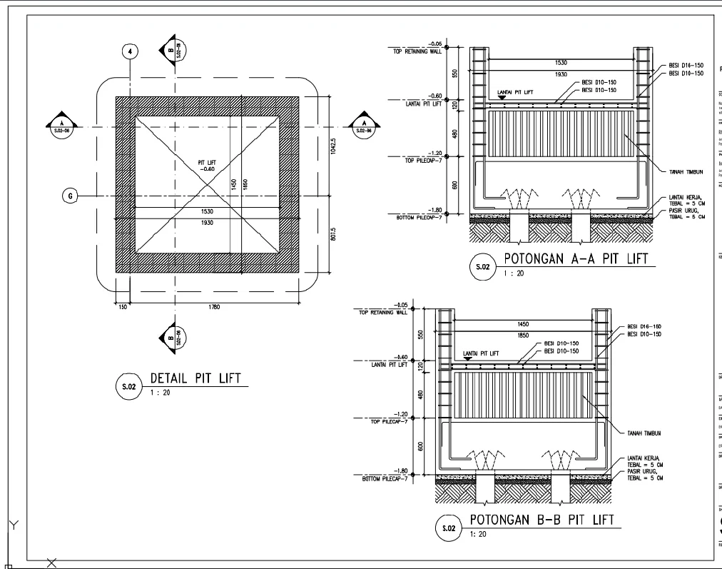
This lift pit detail DWG file provides a comprehensive structural drawing, including plan and sectional details for lift pit construction with a scale of 1 to 20. The plan shows internal dimensions of 1530 mm by 1930 mm with overall outer dimensions approximately 1780 mm and 1042.5 mm, indicating wall thickness and structural boundaries. Section A and Section B illustrate vertical levels such as the top retaining wall at minus 0.05, the floor level at minus 0.60, the top pile cap at minus 1.20, and the bottom pile cap at minus 1.80, ensuring accurate depth execution. Reinforcement details include steel bars D10 and D16 at 150 mm spacing along with the concrete slab and retaining wall structure. The drawing also highlights base preparation layers such as sand fill 5 cm and lean concrete 5 cm with soil backfilling around the structure. Structural elements, including retaining walls, pile caps, and slab thickness, are clearly defined for construction clarity. This AutoCAD DWG drawing is ideal for architects, civil engineers, and contractors for lift pit structural detailing and execution.
Tags
Uploaded by:
Neha
mishra
Ratings & Reviews
Be the first to share your experience with this product. Your review helps others make better decisions!