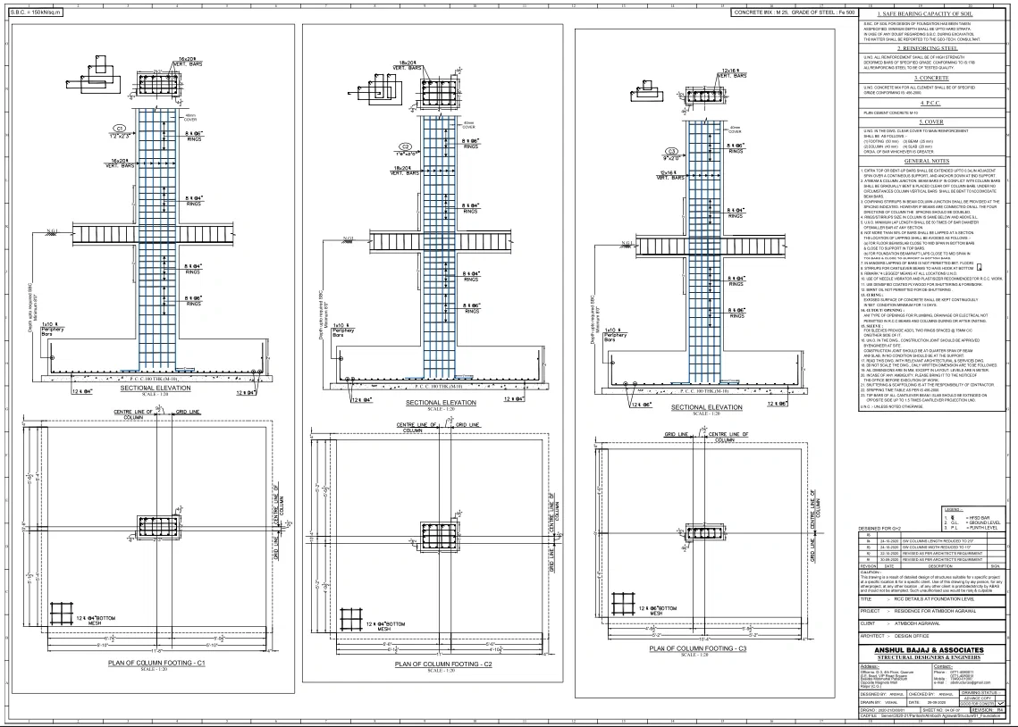
RCC Foundation Detail DWG Column Footing C1 C2 C3 Plan Section

Ratings & Reviews
Be the first to share your experience with this product. Your review helps others make better decisions!
Description
This RCC foundation detail DWG file provides comprehensive structural drawings at the foundation level, including column footing plans C1, C2, and C3, along with sectional elevations showing reinforcement and depth specifications. The drawing includes footing sizes such as 10 ft 8 in, 10 ft 4 in, and 9ft with detailed layout dimensions and centerline grid references for accurate placement. Sectional views illustrate foundation depth up to required safe bearing capacity with minimum depth of 8ft0in and PCC layer of 100 mm thickness using M10 concrete. Reinforcement details include vertical bars, stirrups, and bottom mesh with 12 mm diameter bars and specified spacing, ensuring structural stability. The drawing also defines concrete grade M25 and steel grade Fe500, along with clear cover requirements of 40 mm for footing and 25 mm for beams. Ground level, plinth level, and excavation details are clearly marked for execution. This AutoCAD DWG drawing is ideal for civil engineers, structural designers, and contractors for RCC footing design and construction.
File Type:
DWG
File Size:
252 KB
Category::
Construction
Sub Category::
Reinforced Cement Concrete Details
type:
Gold
Tags
Uploaded by:
Liam
White
Ratings & Reviews
Be the first to share your experience with this product. Your review helps others make better decisions!