Processing Plant Trench Drain Layout DWG 6000 Grid Detail Plan
Description
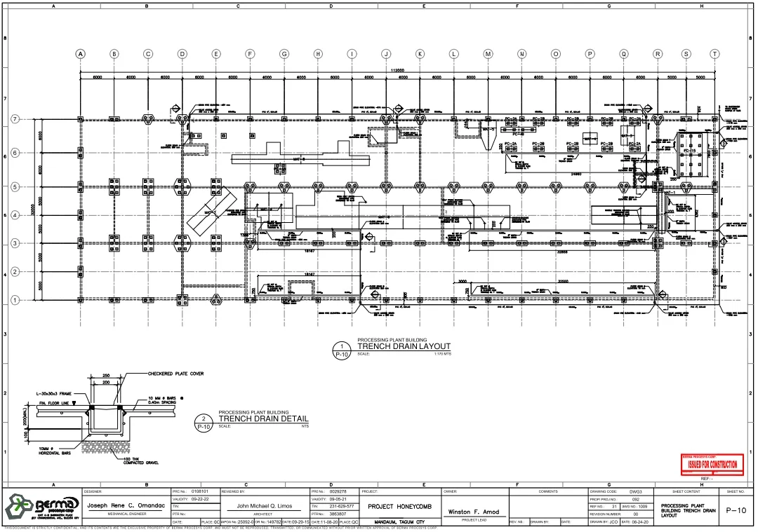
This processing plant trench drain layout DWG file provides a detailed drainage system plan with grid spacing of 6000 mm across multiple axes from A to T, ensuring accurate alignment and installation. The drawing includes a complete trench drain network layout integrated within the processing plant building with clear routing across structural grids and equipment zones. As shown in the trench drain detail on page 1 the section includes a checkered plate cover with 250 mm width supported on L 30x30x3 frame and reinforced with 10 mm diameter bars at 0.40 m spacing along with horizontal reinforcement bars. The trench base is constructed over 100 mm thick compacted gravel, ensuring proper drainage and stability. The layout also defines connection points, flow directions, and integration with plant utilities for effective wastewater management. This AutoCAD DWG drawing is ideal for civil engineers, mechanical engineers, and plant designers for drainage planning and construction execution.
File Type:
DWG
File Size:
641 KB
Category::
Urban Design
Sub Category::
Town Water Treatment Design
type:
Gold

Uploaded by:
Umar
Mehmood