Typical Waterproofing System To Planters Basements Carpark DWG

Ratings & Reviews
Be the first to share your experience with this product. Your review helps others make better decisions!
Description
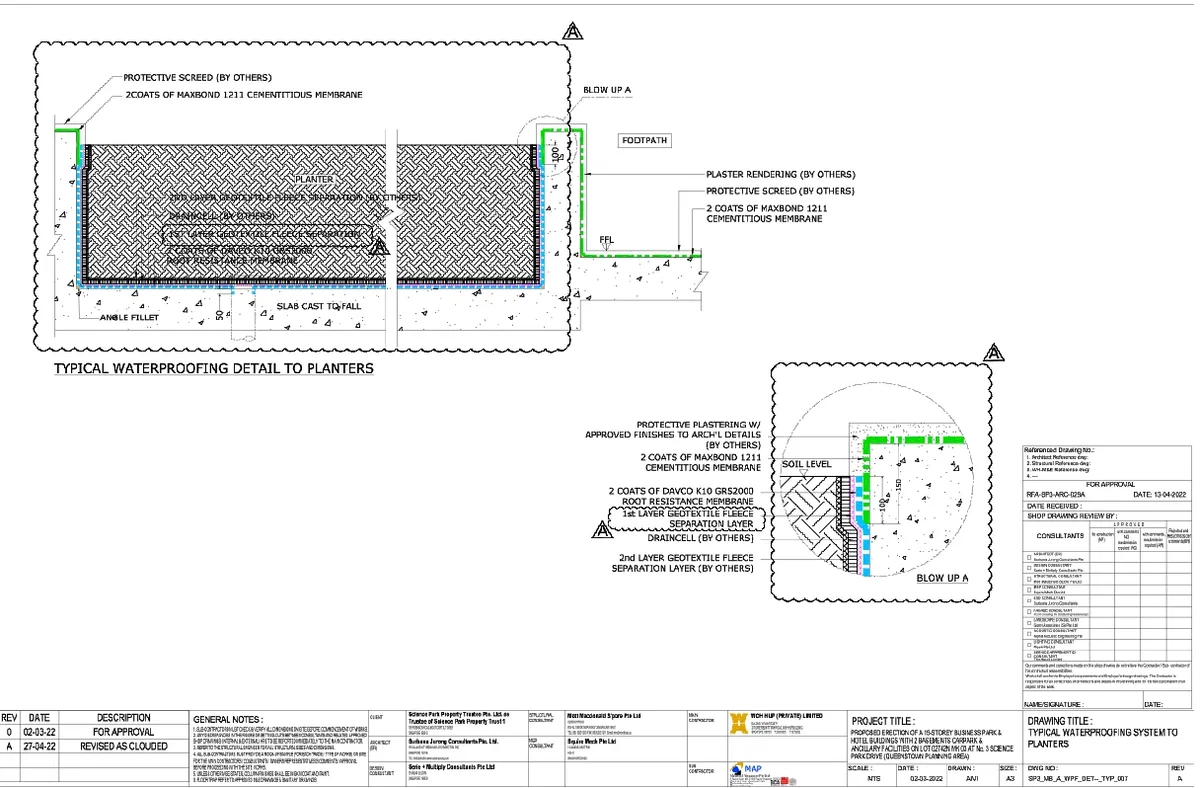
A detailed TYPICAL WATERPROOFING SYSTEM TO PLANTERS BASEMENTS, CARPARK AND ANCILLARY FACILITIES DWG presenting complete construction sections and layered waterproofing system for planter areas integrated with basement and carpark structures. The drawing illustrates a planter box with a slab cast to fall, an angle fillet of 50 mm, and a finished floor level FFL around 100 mm, ensuring proper drainage. Waterproofing system includes 2 coats of Maxbond 1211 cementitious membrane and 2 coats of Davco K10 GRS2000 root resistance membrane applied continuously across base and vertical surfaces. The detail also incorporates first and second layer geotextile fleece separation, a draincell system for water flow, and protective screed and plaster finishes. Blow-up sections clearly show wall-to-slab junction waterproofing with thickness references around 100 mm and 150 mm, including soil level and footpath connections. This TYPICAL WATERPROOFING SYSTEM TO PLANTERS BASEMENTS CARPARK AND ANCILLARY FACILITIES DWG provides accurate material specifications, dimensional references, and construction-ready detailing for architects and engineers.
Tags
Uploaded by:
Umar
Mehmood
Ratings & Reviews
Be the first to share your experience with this product. Your review helps others make better decisions!