Equipment Mounting Rail and Panel Nut AutoCAD DWG Fabrication Detail
Frequently Asked Questions
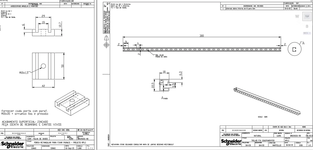
The drawing specifies 12 × 30 mm slotted holes with 60 mm center-to-center spacing for equipment mounting applications.
E-E-A-T & Quality Verification
📝 AI Overview (TL;DR)
This Equipment Mounting Rail AutoCAD DWG includes a 300 mm mounting rail with 12 × 30 mm slotted holes at 60 mm spacing, section and isometric views, plus a rectangular panel nut featuring M10 × 1.5 threading. The drawing provides complete fabrication dimensions, profile details, and assembly references for industrial equipment installation.
💡 First-hand Experience
This drawing has been reviewed for fabrication accuracy and installation practicality. The mounting rail profile, slotted hole layout, panel fixing nut dimensions, threaded connection, section details, and manufacturing views are clearly organized, making the file valuable for mechanical engineers, fabrication teams, electrical panel manufacturers, and CAD professionals.
Ratings & Reviews
Be the first to share your experience with this product. Your review helps others make better decisions!
Description
This Equipment Mounting Rail and Panel Nut AutoCAD DWG provides detailed fabrication drawings for an industrial mounting rail and rectangular panel fixing nut used in equipment installation and enclosure assembly. The drawing includes front, side, section, and isometric views with complete manufacturing dimensions and hole specifications. The mounting rail features an overall 300 mm length, 22.5 mm profile height, 18 mm width, 6.3 mm flange height, 9.2 mm internal opening, 2 mm material thickness, and 12 × 30 mm slotted holes at 60 mm spacing. The panel fixing nut includes 50 × 42 mm dimensions, 29 mm overall width, 19 mm inner width, 12.7 mm height, 6 mm slot depth, and an M10 × 1.5 threaded hole. This AutoCAD DWG file is suitable for industrial fabrication, equipment support systems, electrical panel manufacturing, structural detailing, workshop documentation, and mechanical assembly projects.
Tags
Uploaded by:
Rashmi
Solanki
Frequently Asked Questions
The drawing specifies 12 × 30 mm slotted holes with 60 mm center-to-center spacing for equipment mounting applications.
E-E-A-T & Quality Verification
📝 AI Overview (TL;DR)
This Equipment Mounting Rail AutoCAD DWG includes a 300 mm mounting rail with 12 × 30 mm slotted holes at 60 mm spacing, section and isometric views, plus a rectangular panel nut featuring M10 × 1.5 threading. The drawing provides complete fabrication dimensions, profile details, and assembly references for industrial equipment installation.
💡 First-hand Experience
This drawing has been reviewed for fabrication accuracy and installation practicality. The mounting rail profile, slotted hole layout, panel fixing nut dimensions, threaded connection, section details, and manufacturing views are clearly organized, making the file valuable for mechanical engineers, fabrication teams, electrical panel manufacturers, and CAD professionals.
Ratings & Reviews
Be the first to share your experience with this product. Your review helps others make better decisions!