Industrial Building Fire Hydrant Layout Plan AutoCAD DWG Drawing

Frequently Asked Questions
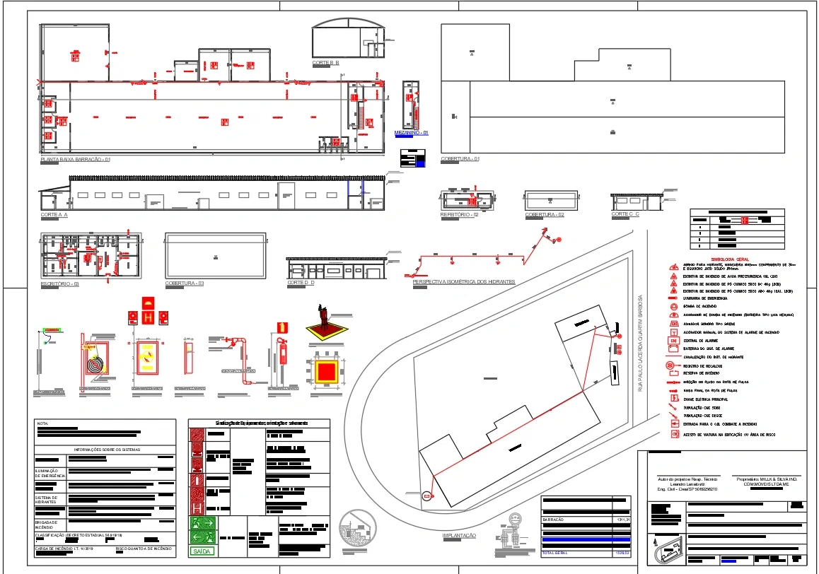
An Industrial Building Fire Hydrant Layout Plan is an AutoCAD DWG drawing that shows the complete fire hydrant system, pipeline routing, fire protection equipment, emergency exits, and safety installations for an industrial facility.
E-E-A-T & Quality Verification
📝 AI Overview (TL;DR)
This AutoCAD DWG drawing includes a complete Industrial Building Fire Hydrant Layout Plan featuring fire hydrant pipelines, equipment layouts, office and mezzanine plans, roof layouts, elevations, sections, fire safety symbols, construction measurements, and installation details for industrial fire protection planning.
💡 First-hand Experience
This drawing was reviewed by examining the industrial site layout, fire hydrant pipeline routing, equipment locations, office and mezzanine layouts, elevations, sectional details, construction dimensions, fire safety legends, and installation references. The coordinated fire protection documentation supports accurate engineering design and construction execution.
Ratings & Reviews
Be the first to share your experience with this product. Your review helps others make better decisions!
Description
This AutoCAD DWG drawing presents a comprehensive Industrial Building Fire Hydrant Layout Plan with complete fire protection system details for an industrial facility. The drawing includes the site layout, building floor plan, roof plans, office layout, mezzanine level, cafeteria layout, elevations, sectional views, and isometric fire hydrant pipeline details. It illustrates the locations of fire hydrants, hose reel cabinets, fire extinguishers, alarm devices, emergency lighting, manual call points, fire safety symbols, evacuation routes, and fire protection equipment legends. The drawing also provides construction dimensions, equipment schedules, installation references, pipeline routing, property boundaries, and detailed fire safety annotations to support accurate planning and coordination. Measured layouts and technical details help ensure efficient fire protection system installation, regulatory compliance, and coordination between architectural, structural, and MEP disciplines.




Tags
Uploaded by:
Neha
mishra
Frequently Asked Questions
An Industrial Building Fire Hydrant Layout Plan is an AutoCAD DWG drawing that shows the complete fire hydrant system, pipeline routing, fire protection equipment, emergency exits, and safety installations for an industrial facility.
E-E-A-T & Quality Verification
📝 AI Overview (TL;DR)
This AutoCAD DWG drawing includes a complete Industrial Building Fire Hydrant Layout Plan featuring fire hydrant pipelines, equipment layouts, office and mezzanine plans, roof layouts, elevations, sections, fire safety symbols, construction measurements, and installation details for industrial fire protection planning.
💡 First-hand Experience
This drawing was reviewed by examining the industrial site layout, fire hydrant pipeline routing, equipment locations, office and mezzanine layouts, elevations, sectional details, construction dimensions, fire safety legends, and installation references. The coordinated fire protection documentation supports accurate engineering design and construction execution.
Ratings & Reviews
Be the first to share your experience with this product. Your review helps others make better decisions!