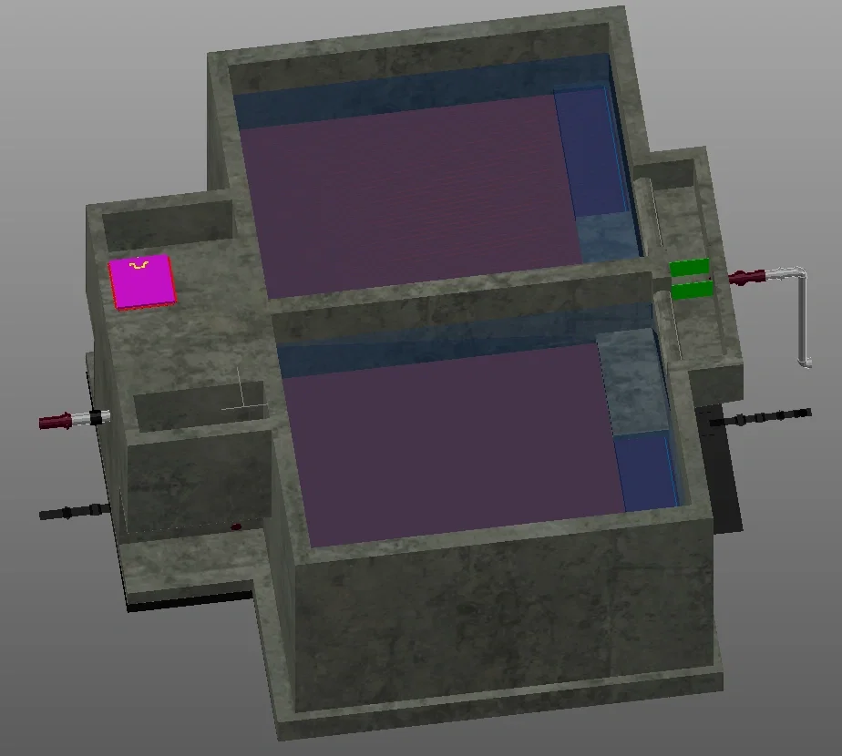
Industrial Water Treatment Tank System 3D AutoCAD DWG Model Design
Tags
Frequently Asked Questions
This drawing includes a detailed 3D industrial water treatment tank system with concrete chambers, partition walls, inlet and outlet pipelines, treatment compartments, and structural elements for engineering and construction projects.
E-E-A-T & Quality Verification
📝 AI Overview (TL;DR)
A detailed 3D AutoCAD DWG model of an industrial water treatment tank system featuring interconnected concrete chambers, inlet and outlet pipelines, partition walls, and treatment compartments for wastewater and utility engineering projects.
💡 First-hand Experience
While reviewing this DWG model, I noticed that the layout focuses on practical engineering functionality rather than visualization alone. The separation of treatment chambers, pipe routing, and concrete structural walls provides a clear understanding of water flow through the system. The organized arrangement of inlet and outlet connections makes the model useful for planning treatment plant installations, equipment coordination, and construction detailing. This type of 3D DWG is especially valuable during project reviews because it allows engineers and designers to identify spatial relationships between structural and mechanical components before construction begins.
Ratings & Reviews
Be the first to share your experience with this product. Your review helps others make better decisions!
Description
This AutoCAD DWG drawing showcases a detailed 3D model of an industrial water treatment tank system designed for wastewater processing, filtration, and liquid storage applications. The model illustrates multiple interconnected concrete chambers, inlet and outlet pipe connections, partition walls, access compartments, and equipment installation areas to support efficient fluid movement and treatment operations. The drawing provides a clear visualization of tank geometry, structural layout, and operational components, making it suitable for planning, engineering analysis, and construction documentation. Engineers and designers can use this DWG model for water treatment plant layouts, sewage treatment facilities, industrial processing systems, environmental engineering projects, and utility infrastructure planning. The organized 3D representation helps improve project coordination, equipment placement, structural detailing, and maintenance planning while ensuring compatibility with AutoCAD and other BIM workflows.

Uploaded by:
Neha mishra
Tags
Frequently Asked Questions
This drawing includes a detailed 3D industrial water treatment tank system with concrete chambers, partition walls, inlet and outlet pipelines, treatment compartments, and structural elements for engineering and construction projects.
E-E-A-T & Quality Verification
📝 AI Overview (TL;DR)
A detailed 3D AutoCAD DWG model of an industrial water treatment tank system featuring interconnected concrete chambers, inlet and outlet pipelines, partition walls, and treatment compartments for wastewater and utility engineering projects.
💡 First-hand Experience
While reviewing this DWG model, I noticed that the layout focuses on practical engineering functionality rather than visualization alone. The separation of treatment chambers, pipe routing, and concrete structural walls provides a clear understanding of water flow through the system. The organized arrangement of inlet and outlet connections makes the model useful for planning treatment plant installations, equipment coordination, and construction detailing. This type of 3D DWG is especially valuable during project reviews because it allows engineers and designers to identify spatial relationships between structural and mechanical components before construction begins.
Ratings & Reviews
Be the first to share your experience with this product. Your review helps others make better decisions!