Sewage Treatment Plant AutoCAD DWG Layout with Sectional Details

Ratings & Reviews
Be the first to share your experience with this product. Your review helps others make better decisions!
Description
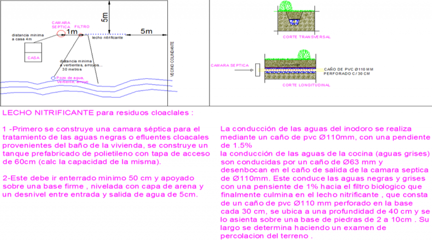
The Sewage Treatment Plant AutoCAD DWG drawing provides a comprehensive technical layout, including sectional views, plan details, and pipeline arrangements. This detailed drawing showcases the layout of treatment chambers, filtration units, and flow channels, enabling accurate planning and implementation for water management and sanitation projects. The DWG file includes cross-sections, inlet and outlet designs, and overall plant dimensions, making it a valuable reference for professional wastewater treatment projects.
This AutoCAD file is ideal for civil engineers, architects, and environmental designers working on drainage systems, infrastructure planning, and water purification facilities. The detailed sections illustrate structural elements, inlet and outlet pipe connections, sedimentation tanks, and clarifier units. Designed with precision, this drawing supports engineers in optimizing the treatment process and ensuring proper facility layout. Download this CAD file now to access ready-to-use technical references for creating sustainable and efficient sewage treatment systems. Perfect for integration in AutoCAD, Revit, and other 3D modeling tools used in engineering and environmental design projects.
Tags
Uploaded by:
Liam
White
Ratings & Reviews
Be the first to share your experience with this product. Your review helps others make better decisions!