Comprehensive Fire Fighting System Layout with Detailed Piping
Tags
Ratings & Reviews
Be the first to share your experience with this product. Your review helps others make better decisions!
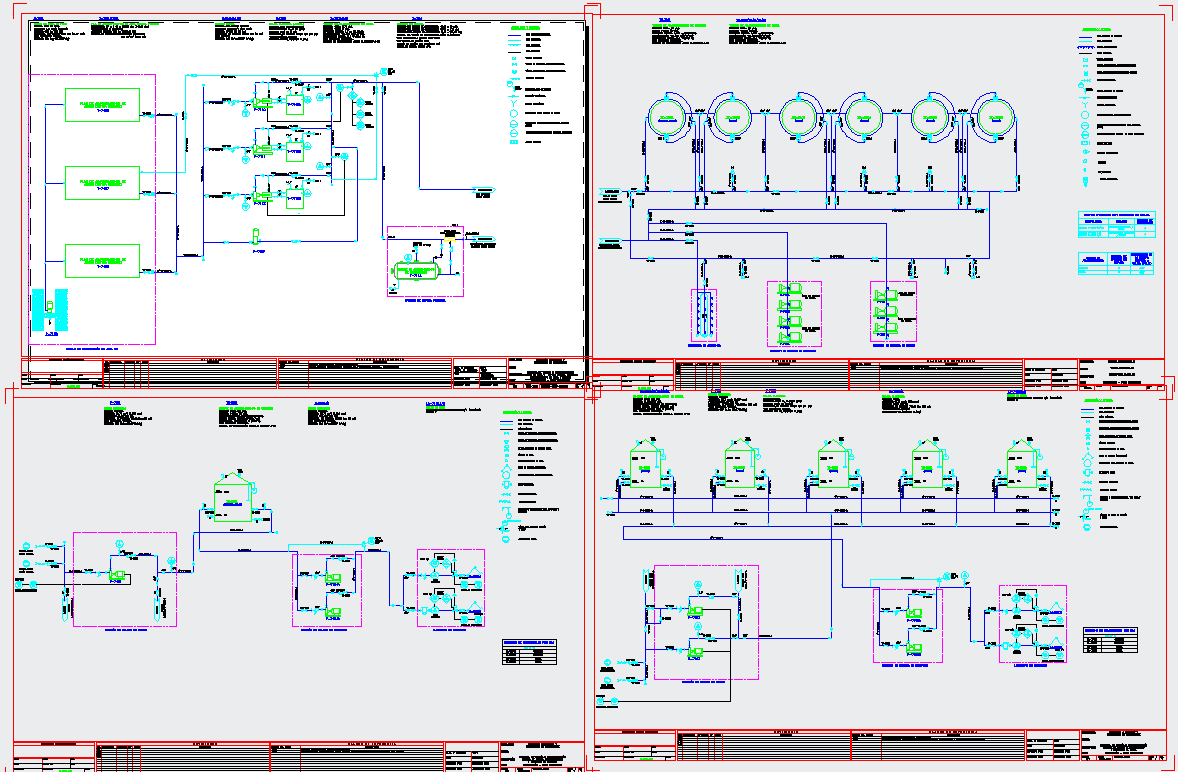
Description
This AutoCAD DWG file is a complete advanced firefighting system layout featuring detailed piping networks, pump connections, tank routing, and equipment symbols essential for safety planning. The design includes multiple fire water storage tanks, a clear line diagram for hydrant systems, sprinkler distribution lines, and pressure maintenance pumps arranged systematically across the sheet. The drawing also highlights flow directions, control valves, strainers, pressure gauges, strainers, and sectional views that help engineers understand equipment placement and pipe sizing. Each diagram is supported with legends, material specifications, component labeling, and a structured title block for technical clarity.
The plan features multiple modules such as pump room connections, hydrant pipelines, sprinkler loops, deluge systems, and emergency control assemblies. The schematic layout also displays vertical risers, isolation valves, test line arrangements, and distribution manifolds designed to maintain consistent water pressure throughout the building. Suitable for high-rise buildings, commercial complexes, industrial facilities, and residential structures, this DWG file offers precise technical detailing for safety engineers, MEP consultants, architects, and contractors. With accurate symbol representation, pipe routing clarity, and equipment integration, this firefighting system drawing is highly valuable for professionals developing reliable and compliant fire protection solutions.

Uploaded by:
Neha mishra
Tags
Ratings & Reviews
Be the first to share your experience with this product. Your review helps others make better decisions!