Gas line station DWG with site layout piping route and equipment
Description
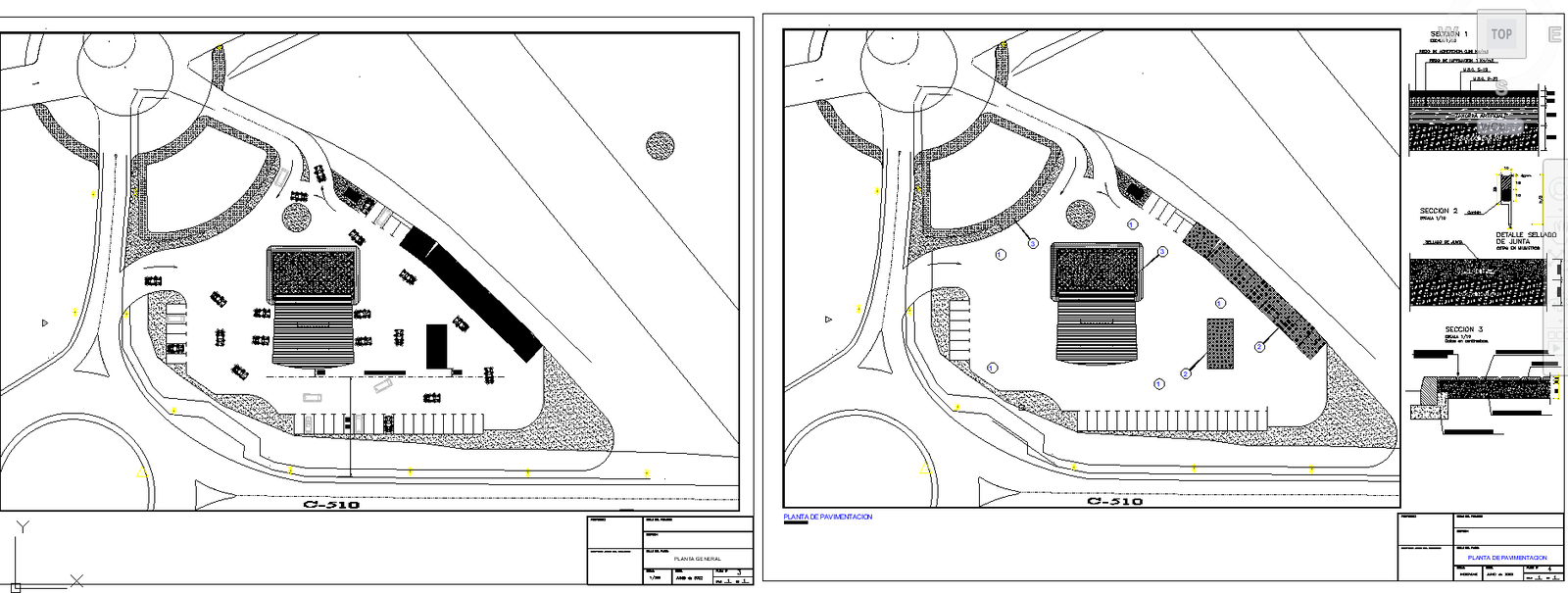
This gas line station DWG file provides a detailed architectural and engineering layout created in AutoCAD format. The drawing includes a complete site plan showing pipe routing, valve chamber placement, pressure control points and utility corridors. Each sheet contains scaled diagrams of the main gas distribution system with clear indications of inlet and outlet connections, safety control units and isolation valves. Equipment layouts include regulators, storage tanks, meters, inspection chambers and monitoring devices, all placed accurately for technical reference.
Structural framing, foundation pads, support platforms and anchoring details are represented to guide engineers during installation. The drawing also displays circulation routes for vehicles and maintenance access points, ensuring operational safety and ease of movement. Utility blocks such as electrical kiosks, safety enclosures and monitoring shelters are included with labelled dimensions. This DWG file is highly valuable for civil engineers, architects, MEP designers and students working on utility infrastructure and industrial service planning. A Cadbull subscription provides access to these detailed gas line station drawings, supporting efficient design development, documentation accuracy and engineering coordination.

Uploaded by:
Fernando
Zapata