Machine Design Drawing with Detailed Sections and Measurements
Tags
Ratings & Reviews
Be the first to share your experience with this product. Your review helps others make better decisions!
Description
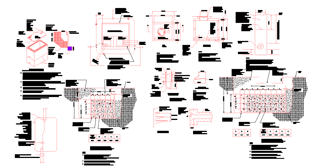
This machine design drawing is provided as a detailed AutoCAD DWG file presenting complete technical detailing with accurate measurements. The drawing includes plan views, sectional views, and component layouts clearly illustrating machine geometry, internal assemblies, and part arrangements. Key elements such as base plates, housings, shafts, fasteners, and internal cavities are shown with precise dimension lines and reference annotations. Section cuts explain internal working clearances, thicknesses, and alignment of mechanical parts, supporting a clear understanding of machine construction. Material zones, fixing points, and load-bearing areas are represented to scale, making the drawing suitable for fabrication and technical coordination.
The machine design drawing further includes enlarged details for critical components, showing tolerances, hole patterns, and joint connections. Measurement markers define overall machine size, component spacing, and installation clearances. Reference grids and labels assist engineers in identifying each part accurately within the assembly. This AutoCAD DWG machine design drawing supports mechanical planning, manufacturing reference, and design review, where clarity of dimensions, sectional detailing, and component relationships is essential.

Uploaded by:
Liam White
Tags
Ratings & Reviews
Be the first to share your experience with this product. Your review helps others make better decisions!