Fluid Piping Detail Layout with Pipe Sizes Valves Flow Direction
Tags
Ratings & Reviews
Be the first to share your experience with this product. Your review helps others make better decisions!
Description
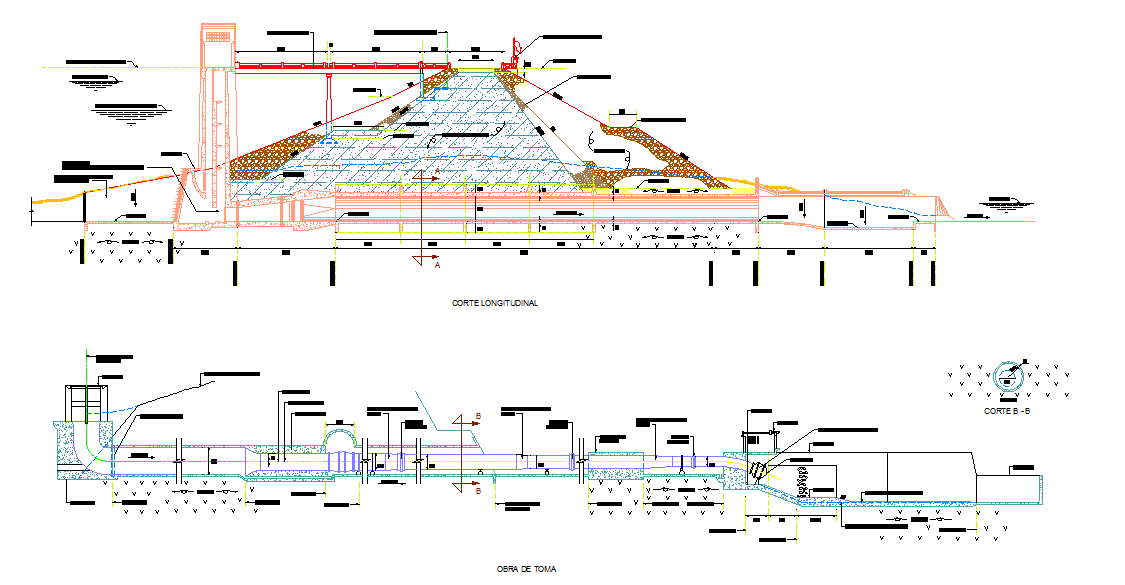
This AutoCAD DWG drawing shows a detailed fluid piping detail layout prepared for engineering and construction use. The drawing clearly illustrates fluid piping routes with accurate pipe sizes, diameter marking,s flow direction arrows, and connection points. It includes elbows, tee reducers, flanges, and control valves arranged as per standard piping practice. Centre line spacing, pipe alignment,t and layout clearances are properly indicated to help architects, civil engineers, and builders understand the complete fluid piping system. The fluid piping detail drawing is suitable for water supply process fluid or utility piping layouts in industrial and building projects.
The fluid piping detail layout also presents elevation and sectional clarity,y where required,d showing vertical and horizontal pipe runs with measured distances. Valve positions, supports, fixing points, and junction details are marked for smooth installation and maintenance planning. This fluid piping detail drawing helps AutoCAD Revi,t and SketchUp users save design time by using a ready reference layout. The drawing supports accurate coordination with structural and architectural plans, making it useful for professional documentation and execution work.
Characters count 201 words

Uploaded by:
Liam White
Tags
Ratings & Reviews
Be the first to share your experience with this product. Your review helps others make better decisions!