Industrial Machinery Design Drawing with Valve and Pipe Section Detail
Tags
Ratings & Reviews
Be the first to share your experience with this product. Your review helps others make better decisions!
Description
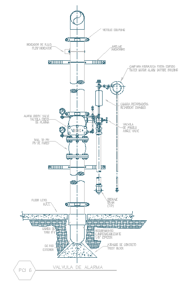
This industrial machinery design drawing provides a detailed vertical section layout prepared in AutoCAD format, clearly illustrating mechanical components, pipe connections, and valve assemblies. The drawing includes a structured arrangement of pipes, flanges, alarm valve assembly, flow indicator, check valve, drain valve, and pressure control components. Floor level reference, underground pipe connection, concrete base support, and anchoring details are clearly shown for accurate installation. All elements are precisely aligned with centerline references and component labeling, helping users understand the functional relationship between mechanical parts and piping systems. The drawing represents a typical machinery installation used for fluid control and monitoring within industrial and utility applications.
This machinery design detail drawing is useful for mechanical engineers, civil engineers, builders, and technical professionals involved in industrial plant design and infrastructure projects. The AutoCAD DWG file supports easy editing, scaling, and coordination with mechanical layouts using AutoCAD, Revit, 3ds Max, or SketchUp. Clear sectional representation improves understanding of equipment positioning, pipe routing, and foundation interface. This drawing assists in planning, execution, and maintenance coordination while following standard mechanical detailing practices. It is a valuable CAD resource for professionals seeking reliable machinery and piping detail drawings through a Cadbull subscription.

Uploaded by:
john kelly
Tags
Ratings & Reviews
Be the first to share your experience with this product. Your review helps others make better decisions!